High-pressure soaking rapid pyrolysis device

A pyrolyzer and pyrolysis reactor technology, applied in the petrochemical field, can solve problems such as low heat transfer efficiency, increased failure rate, and reduced thermal efficiency, and achieve the effects of simple manufacture and installation, smooth discharge, and stable performance

Pending Publication Date: 2018-04-20
北京恒丰亚业科技发展有限公司
View PDF6 Cites 0 Cited by
  • Summary
  • Abstract
  • Description
  • Claims
  • Application Information

AI Technical Summary

Problems solved by technology

At present, fast pyrolyzers are generally divided into reaction devices such as fluidized bed, moving bed, and rotating bed, and use two methods of carrier and carrierless to achieve the temperature distribution of the temperature field and the requirements of the heating rate. The pyrolyzer involves a series of complex processes such as the uniform distribution, mixing, and reaction of the carrier and raw materials, as well as the separation, re-preheating, and re-transportation of the downstream carrier and semi-coke products, resulting in an increase in failure rate and a decrease in overall thermal efficiency
There are also non-carrier indirect heat transfer pyrolyzers, but the heat transfer efficiency is low, and it is difficult to scale up, and more pyrolyzers with rectangular cross-sections are used. This type of pyrolyzer is only suitable for medium and low temperature, normal pressure Under the conditions of high temperature and low pressure, the fast pyrolyzer for high temperature and high pressure still needs to be further developed

Method used


Image

  • High-pressure soaking rapid pyrolysis device
  • High-pressure soaking rapid pyrolysis device

Examples


Embodiment Construction

[0029] In order to enable those skilled in the art to better understand the technical solutions of the present invention, the present invention will be further described in detail below in conjunction with specific examples. Please note that the embodiments described below are exemplary only for explaining the present invention, and should not be construed as limiting the present invention. If no specific technique or condition is indicated in the examples, it shall be carried out according to the technique or condition described in the literature in this field or according to the product specification. The reagents or instruments used were not indicated by the manufacturer, and they were all commercially available conventional products.

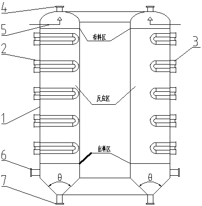
[0030] To meet the requirements of downstream processes, pyrolysis gas needs to be transported at high temperature and high pressure. However, the existing rectangular cross-section heat-carrier-free fast pyrolyzer is only suitable for low-p...


PUM

PropertyMeasurementUnit
thicknessaaaaaaaaaa
diameteraaaaaaaaaa
diameteraaaaaaaaaa

Abstract

The invention specifically relates to a high-pressure soaking rapid pyrolysis device. The high-pressure soaking rapid pyrolysis device comprises a pyrolysis device barrel, a distributing device and heat accumulation type radiant tubes, wherein the heat accumulation type radiant tubes comprise first heat accumulation type radiant tubes and second heat accumulation type radiant tubes, the first heataccumulation type radiant tubes and the second heat accumulation type radiant tubes are arranged on the horizontal plane in a staggered manner, and the lengths of the first heat accumulation type radiant tubes are greater than those of the second heat accumulation type radiant tubes; and each layer of the radiant tubes is provided with a plurality of radiant tubes, each layer of the heat accumulation type radiant tubes are radially and uniformly arranged in the horizontal direction, and the area formed by the annular barrel structure is a reaction area. According to the device, a barrel formis adopted, an ellipsoid structure is adopted on the top, a conical structure is adopted at the bottom, the pressure resistance and the high temperature resistance are higher, and the discharge is smooth; and the device is applicable for low pressure and high pressure environments, and is also applicable for low temperature and high temperature environments.

Description

technical field [0001] The invention belongs to the technical field of petrochemicals, and in particular relates to a high-pressure soaking fast pyrolyzer. Background technique [0002] Rapid pyrolysis refers to the rapid heating of the material to the temperature required for pyrolysis under the condition of no oxygen or limited oxygen, so that the carbon-containing polymers undergo rapid chemical bond breaking reaction, and the working environment of high temperature and high pressure will increase the yield of pyrolysis products. Spawn rate has been greatly improved. At present, fast pyrolyzers are generally divided into reaction devices such as fluidized bed, moving bed, and rotating bed, and use two methods of carrier and carrierless to achieve the temperature distribution of the temperature field and the requirements of the heating rate. The pyrolyzer involves a series of complex processes such as the uniform distribution, mixing, and reaction of the carrier and raw m...

Claims


Application Information

Patent Timeline
Patent Type & Authority Applications(China)
IPC IPC(8): C10B53/00C10B47/00C10B57/00
CPCC10B47/00C10B53/00C10B57/00
Inventor 常胜良谢善清李生忠林景龙吴道洪
Owner 北京恒丰亚业科技发展有限公司
Why Eureka
Try Eureka