Eureka AIR delivers breakthrough ideas for toughest innovation challenges, trusted by R&D personnel around the world.

A Small s/c Dual Band Planar Conical Helical Composite Antenna

A compound antenna and helical antenna technology, applied in antennas, loop antennas, electrical components, etc., can solve the problems of miniaturization, high efficiency and high gain, circular polarization and wide beam, etc., to achieve flexible design freedom, Good standing wave performance, high gain effect

Active Publication Date: 2020-01-14
HUBEI SANJIANG SPACE XIANFENG ELECTRONICS&INFORMATION CO LTD
View PDF6 Cites 0 Cited by
  • Summary
  • Abstract
  • Description
  • Claims
  • Application Information

AI Technical Summary

Problems solved by technology

[0004] For the above defects or improvement needs of the prior art, the present invention provides a small S / C dual-band planar cone-helix compound antenna combining the planar helical antenna and the conical helical antenna, the purpose of which is to solve the existing separate design The planar helical antenna or conical helical antenna cannot take into account the problems of miniaturization, high efficiency, high gain, circular polarization and wide beam

Method used


Image

  • A Small s/c Dual Band Planar Conical Helical Composite Antenna
  • A Small s/c Dual Band Planar Conical Helical Composite Antenna
  • A Small s/c Dual Band Planar Conical Helical Composite Antenna

Examples


Embodiment Construction

[0036] In order to make the object, technical solution and advantages of the present invention clearer, the present invention will be further described in detail below in conjunction with the accompanying drawings and embodiments. It should be understood that the specific embodiments described here are only used to explain the present invention, not to limit the present invention. In addition, the technical features involved in the various embodiments of the present invention described below can be combined with each other as long as they do not constitute a conflict with each other.

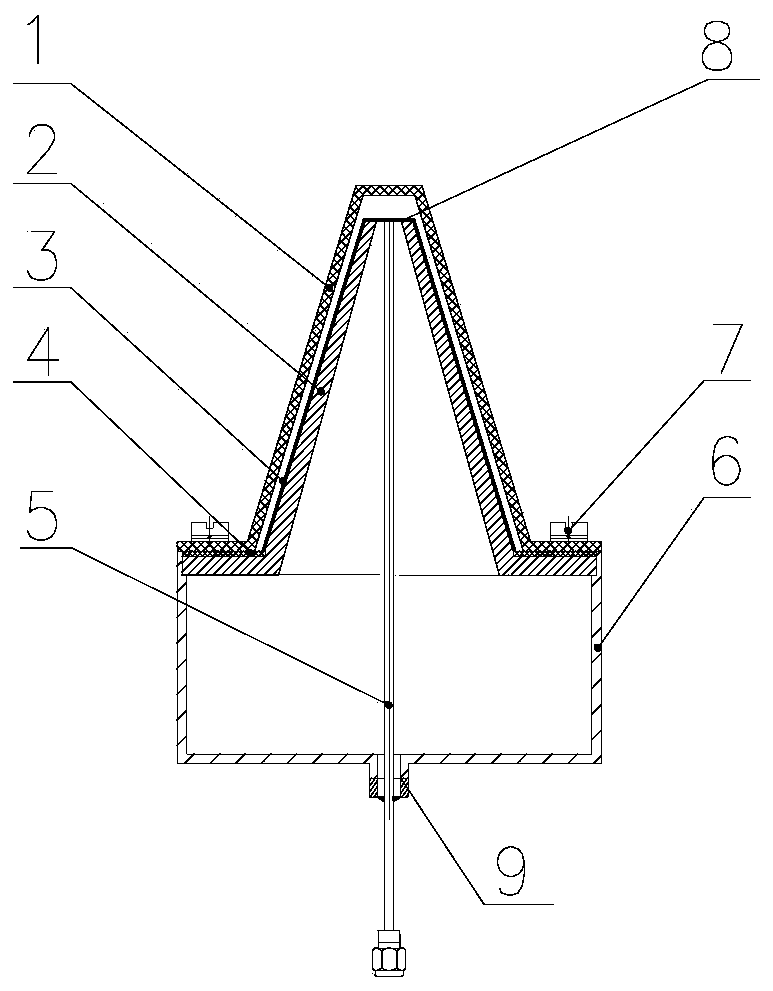
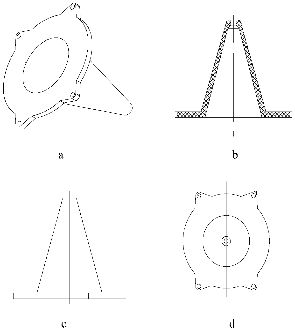
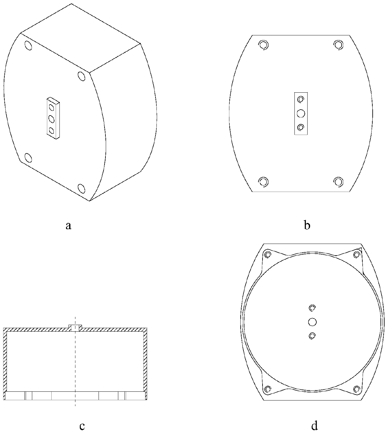
[0037] figure 1 It is a structural cross-sectional view of a small S / C dual-band planar cone-helix compound antenna provided by an embodiment of the present invention, including a radome 1, a dielectric seat 2, a cone-spiral flexible printed board 3, a plane spiral printed board 4, a balun 5, Metal seat 6, fastener 7, feeder plate 8 and fixing block 9;

[0038] The conical spiral flexible prin...


PUM


Abstract

The invention discloses a small-sized S / C dual-band planar / cone spiral composite antenna. The small-sized S / C dual-band planar / cone spiral composite antenna comprises a hollow cone-shaped dielectric holder, a feeding board, a cone spiral antenna, a planar spiral antenna, a metal seat, and a balun; the feeding board is arranged at the top of the dielectric holder; the cone spiral antenna is printedon a first substrate which is attached onto the conical surface of the dielectric holder; the planar spiral antenna is printed on a second substrate which is arranged on the base of the dielectric holder and is fixedly connected with the connection portion of the first substrate; the metal seat has a hollow cavity; an opening is formed at the top of the metal seat; the dielectric holder is fixedon the top of the metal seat; a through hole is formed at the bottom of the metal seat; one end of the balun passes through the bottom of the metal seat and the through hole at the top of the dielectric holder; and the metal shielding layer and inner conductor of the balun are respectively welded to two metallized through holes of the feeding board. According to the small-sized S / C dual-band planar / cone spiral composite antenna of the present invention, the planar spiral antenna and the cone spiral antenna are combined, and therefore, the composite antenna simultaneously satisfies performancerequirements of small size, high efficiency, high gain, circular polarization, and wide beam.

Description

technical field [0001] The invention belongs to the technical field of microwave antennas, and more specifically relates to a small S / C dual-band planar cone-helical compound antenna. Background technique [0002] The helical antenna can not only achieve wide beam circular polarization, but also has the advantages of small size, light weight and stable structure, so it has been widely used in the field of satellite communication. [0003] Helical antennas include planar helical antennas and three-dimensional helical antennas, such as conical helical antennas, but the power capacity and radiation efficiency of planar helical antennas are low, and the gain at the low end of frequency is usually less than 0 decibels; The angular axis is poor, and the beam width changes significantly with frequency; in the S / C band, improving the gain of the antenna in a wide frequency band and wide angle is an important way to meet the effective radiation power index and improve the transceiver...

Claims


Application Information

Patent Timeline
Patent Type & Authority Patents(China)
IPC IPC(8): H01Q7/00H01Q1/38
CPCH01Q1/38H01Q7/00
Inventor 万奇龙邱世锋李温娜高天阳
Owner HUBEI SANJIANG SPACE XIANFENG ELECTRONICS&INFORMATION CO LTD
Why Eureka
Eureka Blog
Learn More