[0005]The present invention provides a multi-speed sprocket assembly for engaging a bicycle chain displaceable by a derailleur. The multi-speed sprocket assembly generally includes at least one smaller sprocket and at least one larger sprocket. The larger sprocket includes first and second transitional segments for alternatively receiving a shifting chain segment of the bicycle chain shifting from the smaller sprocket to the larger sprocket. The first transitional segment includes a first run-on ramp configured to receive an outer link plate of the shifting chain segment. The run-on ramp has a first
support point configured to bend the shifting chain segment at a first angle to position a first chain roller against a no-load tooth flank of the larger sprocket while a second chain roller rests against a load tooth flank of the smaller sprocket. The second transitional segment includes a second run-on ramp configured to receive the outer link plate of the shifting chain segment. The second run-on ramp has a second support point configured to bend the shifting chain segment at a second angle to position the first chain roller against the no-load tooth flank of the larger sprocket while the second chain roller rests against the load tooth flank of the smaller sprocket.
[0006]The multi-speed sprocket assembly facilitates the shifting of the chain from a smaller sprocket to a larger sprocket, especially when the number of teeth of the larger sprocket, including the
teeth missing in missing-tooth gaps, is not integer divisible by the difference between the number of teeth of the larger sprocket and the adjacent smaller sprocket, including the missing teeth. When the chain is shifting between sprockets, the shifting chain segment bends at an angle at the support point on the run-on ramp of the larger sprocket. An offset that is not ideal or an excessively
short distance of the two roller support points on the smaller and larger sprockets can be corrected by increasing the bend angle of the shifting chain segment. This can be accomplished by displacing the support point of the
chain link plate on the run-on ramp. On the one hand, the angle of support is larger when the distance of the support point from the rotation of axis of the sprocket is reduced. On the other hand, the angle of support is smaller when the distance is increased.
[0006]The multi-speed sprocket assembly facilitates the shifting of the chain from a smaller sprocket to a larger sprocket, especially when the number of teeth of the larger sprocket, including the teeth missing in missing-tooth gaps, is not integer divisible by the difference between the number of teeth of the larger sprocket and the adjacent smaller sprocket, including the missing teeth. When the chain is shifting between sprockets, the shifting chain segment bends at an angle at the support point on the run-on ramp of the larger sprocket. An offset that is not ideal or an excessively
short distance of the two roller support points on the smaller and larger sprockets can be corrected by increasing the bend angle of the shifting chain segment. This can be accomplished by displacing the support point of the
chain link plate on the run-on ramp. On the one hand, the angle of support is larger when the distance of the support point from the rotation of axis of the sprocket is reduced. On the other hand, the angle of support is smaller when the distance is increased.
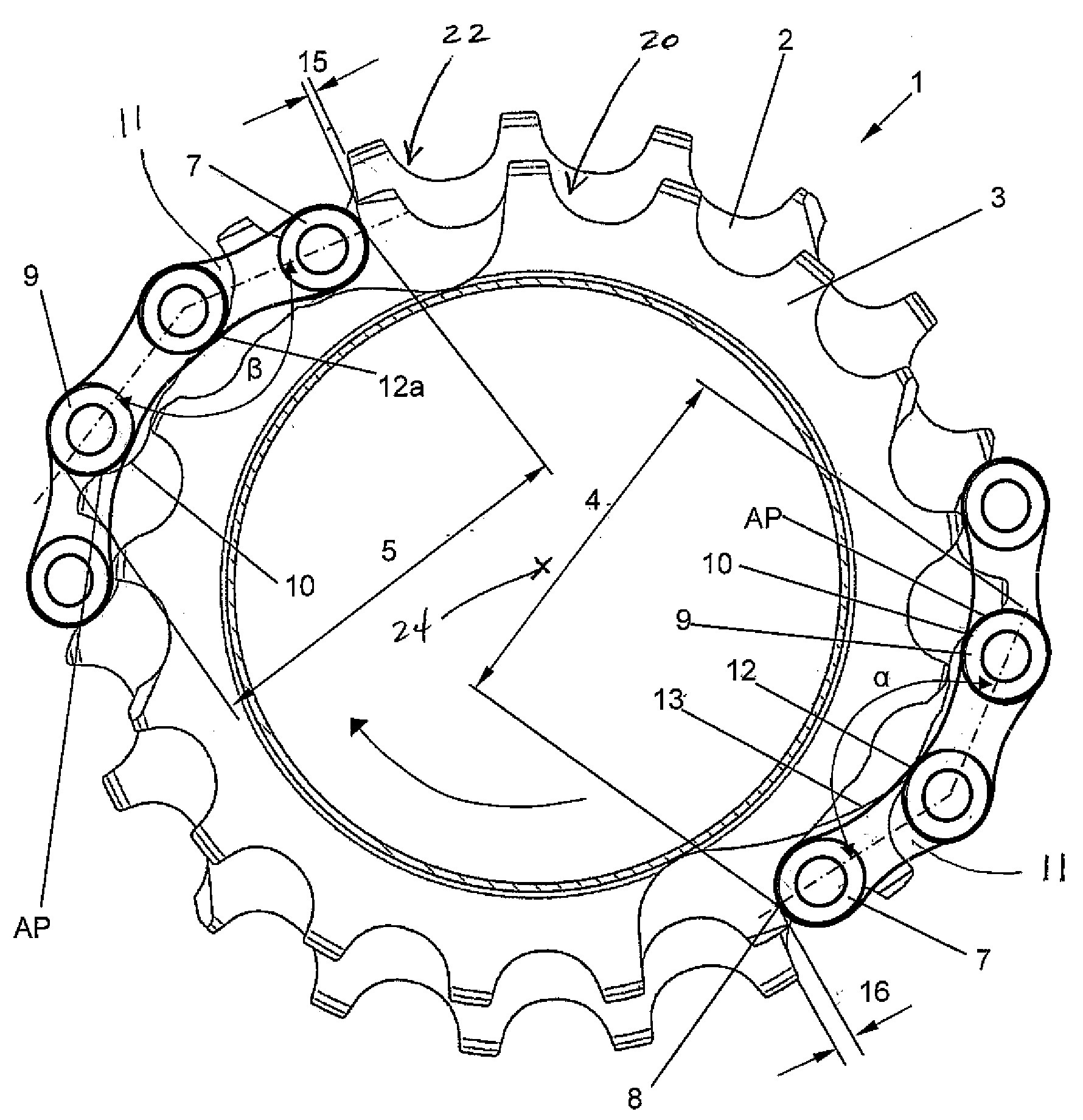
[0006]The multi-speed sprocket assembly facilitates the shifting of the chain from a smaller sprocket to a larger sprocket, especially when the number of teeth of the larger sprocket, including the teeth missing in missing-tooth gaps, is not integer divisible by the difference between the number of teeth of the larger sprocket and the adjacent smaller sprocket, including the missing teeth. When the chain is shifting between sprockets, the shifting chain segment bends at an angle at the support point on the run-on ramp of the larger sprocket. An offset that is not ideal or an excessively short distance of the two roller support points on the smaller and larger sprockets can be corrected by increasing the bend angle of the shifting chain segment. This can be accomplished by displacing the support point of the chain link plate on the run-on ramp. On the one hand, the angle of support is larger when the distance of the support point from the rotation of axis of the sprocket is reduced. On the other hand, the angle of support is smaller when the distance is increased.
[0006]The multi-speed sprocket assembly facilitates the shifting of the chain from a smaller sprocket to a larger sprocket, especially when the number of teeth of the larger sprocket, including the teeth missing in missing-tooth gaps, is not integer divisible by the difference between the number of teeth of the larger sprocket and the adjacent smaller sprocket, including the missing teeth. When the chain is shifting between sprockets, the shifting chain segment bends at an angle at the support point on the run-on ramp of the larger sprocket. An offset that is not ideal or an excessively short distance of the two roller support points on the smaller and larger sprockets can be corrected by increasing the bend angle of the shifting chain segment. This can be accomplished by displacing the support point of the chain link plate on the run-on ramp. On the one hand, the angle of support is larger when the distance of the support point from the rotation of axis of the sprocket is reduced. On the other hand, the angle of support is smaller when the distance is increased.

