Pressure regulating system of hydraulic drive air conditioner of crane cab

A pressure regulation and control room technology, applied in the safety of fluid pressure actuation system, fluid pressure actuation system components, fluid pressure actuation system testing, etc. and other problems, to achieve the effect of small power loss, stable operation, and operation and normal protection.

Pending Publication Date: 2018-04-03
JIANGSU XCMG CONSTR MASCH RES INST LTD
View PDF0 Cites 6 Cited by
  • Summary
  • Abstract
  • Description
  • Claims
  • Application Information

AI Technical Summary

Problems solved by technology

[0006] Purpose: In order to overcome the deficiencies in the prior art, the present invention provides a pressure regulating system for a hydraulically driven air conditioner in the crane control room, which solves the problem of sudden fluctuations in the engine speed of the main engine during the use of the existing hydraulically driven air conditioner. The impact problem caused by the change of pressure and flow of the hydraulic system, the change of pressure and flow not only causes the speed fluctuation of the air conditioner motor, impacts the air conditioner compressor, affects the work of the air conditioner, but also increases the load of the main engine, resulting in insufficient power of the main engine , and even severe cases may cause bursting of supporting hydraulic pipelines

Method used


Image

  • Pressure regulating system of hydraulic drive air conditioner of crane cab
  • Pressure regulating system of hydraulic drive air conditioner of crane cab

Examples


Embodiment Construction

[0021] The present invention will be further described below in conjunction with specific examples.

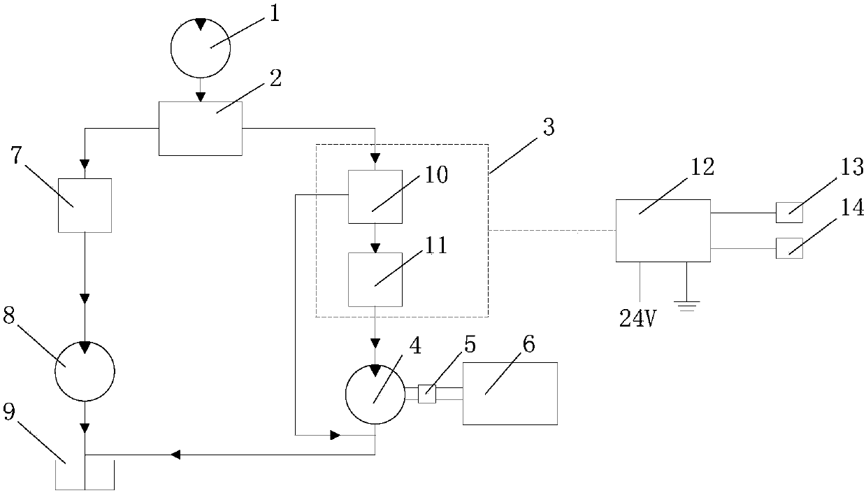
[0022] Such as figure 1 As shown, it is a pressure regulation system for a hydraulically driven air conditioner in a crane control room, including a hydraulic pump 1, a proportional distribution valve 2, an electromagnetic control valve 3 (the electromagnetic control valve 3 includes a relief valve 10 and a throttle valve 11), an air conditioner Motor 4, coupling 5, air conditioner compressor 6, rotary buffer valve 7, rotary motor 8, oil return tank 9, air conditioner control unit 12. Among them, the oil outlet of the main engine hydraulic pump 1 is connected with the oil inlet of the proportional distribution valve 2, and after the oil is discharged from the proportional distribution valve 2, it is divided into two circuits, one of which passes through the hydraulic pipeline and is composed of a relief valve 10 and a throttle valve 11 The electromagnetic control valve 3 in t...


PUM


Abstract

The invention discloses a pressure regulating system of a hydraulic drive air conditioner of a crane cab. A hydraulic pump oil outlet of a host machine is divided into two paths through a proportionalvalve; one path is connected with an air conditioner motor through an electromagnetic control valve formed by a hydraulic pipeline, an overflow valve and a throttle valve, the air conditioner motor drives an air conditioner compressor to operate through a coupler, and the electromagnetic control valve is regulated and controlled through an air conditioner control unit according to acquired valuesof a pressure sensor and a temperature sensor; the other path is connected with a rotary motor through a hydraulic pipeline and a rotary buffer valve. The control valve formed by the overflow valve and the throttle valve is connected with the control unit so as to realize a pressure safety protection function on the air conditioner motor, the pressure is automatically regulated, and the air conditioner system operates stably and is normally switched off under protection. The air conditioner motor is connected with the air conditioner compressor through the coupler so as to drive the air conditioner compressor to operate stably, so that a cooling performance of the air conditioner is realized.

Description

technical field [0001] The invention relates to the technical field of air conditioners for cranes, in particular to a pressure regulating system for a hydraulically driven air conditioner in a crane control room. Background technique [0002] Generally, the upper part of the crane has no power (such as engine, motor, etc.). At present, the air conditioner used in the upper part of the crane generally chooses hydraulic drive. The existing pressure oil of the upper hydraulic system is used to switch through the electro-hydraulic valve to drive the air conditioner. The motor rotates, and then drives the belt pulley to rotate, and the belt rotates to drive the air conditioner compressor to rotate, thereby realizing the cooling function of the air conditioner compressor. [0003] The hydraulically driven air conditioner is connected in series in the hydraulic oil circuit of the main engine. When the engine speed of the main engine fluctuates suddenly, it is easy to cause sudden ...

Claims


Application Information

Patent Timeline
IPC IPC(8): B60H1/00B60H1/32F15B21/08F15B13/06F15B11/16F15B19/00F15B20/00
CPCF15B11/161F15B13/06F15B19/00F15B20/007F15B21/087B60H1/00357B60H1/00735B60H1/00885B60H1/3208B60H1/3226
Inventor 蔡彧胡传正左帅
Owner JIANGSU XCMG CONSTR MASCH RES INST LTD
Why Eureka
Try Eureka