Horizontal liquefied gas sweetening tank

A technology for liquefied gas and desulfurization, which is applied in gas fuel, gas treatment, chemical instruments and methods, etc., can solve the problems of increased mercaptan content, increased liquefied gas processing capacity, unqualified liquefied gas sulfur content, etc. Convenience, compact structure, and the effect of shortening the construction period

Active Publication Date: 2018-04-03
SINOPEC ENG +1
View PDF5 Cites 0 Cited by
  • Summary
  • Abstract
  • Description
  • Claims
  • Application Information

AI Technical Summary

Problems solved by technology

Many enterprises are faced with the bottleneck that the processing capacity of liquefied petroleum gas increases or the content of mercaptans increases, and the sulfur content of liquefied petroleum gas cannot be fully processed or the sulfur content of the processed liquefied petroleum gas is unqualified.

Method used


Image

  • Horizontal liquefied gas sweetening tank
  • Horizontal liquefied gas sweetening tank
  • Horizontal liquefied gas sweetening tank

Examples


Embodiment approach

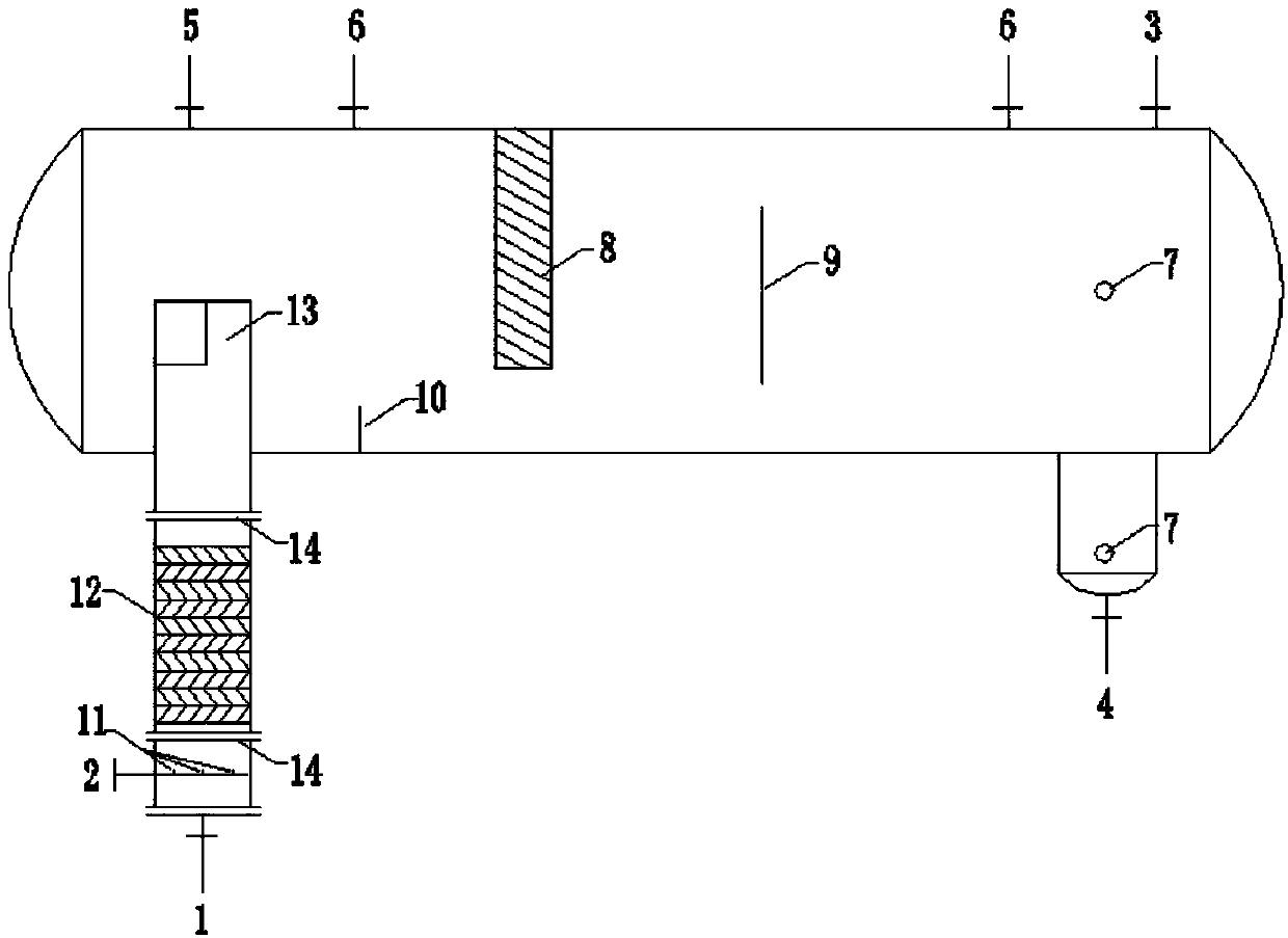
[0033] According to one embodiment, the cross-sectional area of ​​the extraction element 12 and the buffer tube 13 is 0.005-0.126m 2 .

[0034] In addition, the distance between the buffer pipe 13 and the tangent line on one side of the sweetening tank should be as short as possible according to the requirements of equipment manufacturing, which can further reduce the footprint of the horizontal liquefied gas sweetening tank.

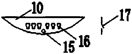
[0035] As a preferred solution, such as image 3 As shown, the overflow plate 10 is a bow-shaped plate. The overflow plate 10 is provided with a guide hole 15 and a trapezoidal hole 16. The trapezoidal hole 16 is wide at the top and narrow at the bottom and has a hole cover 17. The hole cover 17 is obliquely downward and overflowing. The flow plate 10 forms an included angle of 15-30 degrees. The guide hole 15 is preferably one, and the trapezoidal hole 16 is preferably multiple.

[0036] As a preferred solution, the height of the overflow plate 10 i...

Embodiment

[0047] The discharge liquefied gas flow rate of a liquefied gas extraction tower in a factory is 19995 kg / h, and the mass content of mercaptan sulfur is 45ppm, that is, the amount calculated in terms of mercaptan sulfur is 0.9 kg / h, and the mass content of mercaptan sulfur is not greater than 10ppm product index requirements.

[0048] According to this embodiment figure 1 The horizontal liquefied gas sweetening tank shown (combined with Figure 2 to Figure 4 ) to remove the mercaptans in the discharged liquefied gas. Among them, the specification of the tank body is Φ2800×6000, and the cross-sectional area of ​​the extraction element 12 and the buffer tube 13 is 0.018m 2 , The packing height is 2.2m. The horizontal liquefied gas sweetening tank is connected in series after the liquefied gas extraction tower.

[0049] The mercaptan-containing liquefied gas and lye enter the liquefied gas sweetening tank from liquefied gas inlet 1 and lye inlet 2 respectively (the flow ratio...


PUM


Abstract

The invention provides a horizontal liquefied gas sweetening tank. The horizontal liquefied gas sweetening tank comprises a tank body, an extraction unit and a separation unit, wherein the extractionunit comprises a feed assembly, an extraction component and a buffer tube which are connected sequentially, and a liquefied gas inlet as well as an alkali liquor inlet provided with a feed nozzle is formed in the feed assembly; the separation unit comprises an overflow plate, a coalescence plate and a baffle plate which are arranged sequentially in the material flow direction, the overflow plate is fixed at the bottom of the tank body, the coalescence plate is fixed at the top of the tank body, and the baffle plate is arranged in the middle of the tank body. The treatment capacity of a liquefied gas sweetening system can be improved by adopting the horizontal liquefied gas sweetening tanks in parallel connection or series connection under the condition that the original liquefied gas sweetening process is not changed much, and the horizontal liquefied gas sweetening tank has the characteristics that assembling is simple, piping is convenient and the like.

Description

technical field [0001] The invention belongs to the field of deep processing of liquefied petroleum gas, and in particular relates to a horizontal liquefied gas sweetening tank. Background technique [0002] In the production and processing process of petrochemical enterprises, the liquefied gas produced from catalytic or coking units contains a large amount of mercaptans. Mercaptans are not only smelly, but also corrosive; It is necessary to perform sweetening treatment on the liquefied gas, so that the content of mercaptan sulfur in the treated liquefied gas can meet the target requirements of downstream devices or product liquefied gas. [0003] At present, petrochemical companies mostly use extraction towers as the main equipment for sweetening liquefied gas. In recent years, due to reasons such as the inferior quality of crude oil and the need for product structure adjustment, enterprises have upgraded catalytic or coking units, not only the output of liquefied petrole...

Claims


Application Information

Patent Timeline
IPC IPC(8): B01D53/48B01D53/78B01D53/96C10L3/12
CPCB01D53/485B01D53/78B01D53/96B01D2257/306C10L3/12
Inventor 张竹梅王宁
Owner SINOPEC ENG
Why Eureka
Try Eureka