Monitoring system for line protective cabinet

A monitoring system and protection cabinet technology, applied in signal transmission systems, measuring devices, instruments, etc., can solve the problems of increased labor burden, inaccurate manual monitoring, and inability to send people to monitor at special time, so as to reduce labor burden and achieve accurate results Effect

Inactive Publication Date: 2018-03-23
杜荷昌
View PDF6 Cites 0 Cited by
  • Summary
  • Abstract
  • Description
  • Claims
  • Application Information

AI Technical Summary

Problems solved by technology

[0002] The line protection cabinet is a kind of secondary equipment used to monitor and protect the safety of the operating circuit. The existing line protection cabinet mainly monitors and protects the current and voltage in the circuit and ignores the occurrence of its own problems, so it cannot be activated in time. It has the function of monitoring and alarming; when the existing line protection cabinet is running, it is impossible to send people to monitor it all the time, which not only increases the labor burden, but also the manual monitoring is inaccurate; the temperature and humidity of the environment where the line protection cabinet is located Its operation also has a great impact, so now a monitoring system for line protection cabinets is needed, which can not only perform remote monitoring, reduce the labor burden, but also have more accurate monitoring effects, timely alarms, equipped with unique display and storage The printing module adds functions to the traditional monitoring system, so that people can intuitively understand the specific information in the monitored line protection cabinet, leaving cumbersome steps such as statistics and calculations, which is more convenient

Method used


Image

  • Monitoring system for line protective cabinet
  • Monitoring system for line protective cabinet
  • Monitoring system for line protective cabinet

Examples


Embodiment Construction

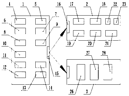
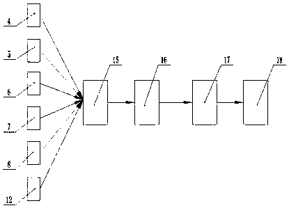
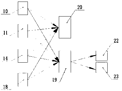
[0021] The present invention is specifically described below in conjunction with accompanying drawing, as Figure 1-5As shown, a monitoring system for a line protection cabinet includes a total monitoring unit module 1, a signal transmission alarm and display module 2 and a storage printing module 3, and the total monitoring unit module 1 is provided by a current input of the line protection cabinet The voltage and current detection module 4 at the terminal and the current output terminal, the current sensor 5 and the voltage sensor 6 located in the line protection cabinet and between the wire connections of different parts, are located in the line protection cabinet and are respectively located at the current input terminal and the current The frequency tester 7 and the current wavelength detector 8 at the output end, the infrared camera 9 arranged at the upper end of the inner cavity of the line protection cabinet, the infrared thermal imager 10 arranged around the inner cavi...


PUM


Abstract

The invention discloses a monitoring system for a line protective cabinet. The system comprises a general monitoring unit module, a signal transfer, alarm and display module and a storing and printingmodule. The general monitoring unit module is composed of a voltage and current detection module, a current sensor, a voltage sensor, a frequency tester, a current wavelength detector, an infrared camera, an infrared thermal imaging instrument, a temperature and humidity sensor, an electric quantity recorder, a GPS positioning module and a door magnetism detection module. The signal transfer, alarm and display module is composed of a first signal processing module, a computing chip, an alarm predicting module, a remote wireless alarm module, a liquid crystal signal display, an alarm indicating lamp and an alarming loudspeaker. The storing and printing module is composed of a second signal processing module, a storage chip and a printing module. The monitoring system has the advantages ofsimple structure and high practicality.

Description

technical field [0001] The invention relates to the field of line protection equipment monitoring, in particular to a monitoring system for line protection cabinets. Background technique [0002] The line protection cabinet is a kind of secondary equipment used to monitor and protect the safety of the operating circuit. The existing line protection cabinet mainly monitors and protects the current and voltage in the circuit and ignores the occurrence of its own problems, so it cannot be activated in time. It has the function of monitoring and alarming; when the existing line protection cabinet is running, it is impossible to send people to monitor it all the time, which not only increases the labor burden, but also the manual monitoring is inaccurate; the temperature and humidity of the environment where the line protection cabinet is located Its operation also has a great impact, so now a monitoring system for line protection cabinets is needed, which can not only perform re...

Claims


Application Information

Patent Timeline
IPC IPC(8): G01D21/02G08C17/02
CPCG01D21/02G08C17/02
Inventor 杜荷昌
Owner 杜荷昌
Why Eureka
Try Eureka