
A vacuum continuous melting and casting device for copper alloy

A technology of vacuum smelting and vacuum casting, which is applied in the field of copper alloy casting, which can solve the problems of unclean metal casting, influence of casting process, inconvenient casting process, etc., achieve sufficient and uniform alloy composition, ensure stable casting process, and facilitate the replacement of alloys.

Active Publication Date: 2019-05-31
JIANGXI UNIV OF SCI & TECH
View PDF11 Cites 0 Cited by
  • Summary
  • Abstract
  • Description
  • Claims
  • Application Information

AI Technical Summary

Problems solved by technology

This design is suitable for the production of pure metals, but not for the production of alloys, because the smelting of alloys requires a sufficient homogenization process, sufficient mixing of alloying elements, and sufficient standing time. The method of casting while feeding is obviously difficult to achieve uniformity
2. Due to the large impact of the added cold material on the temperature of the melt during feeding, it will have a great impact on the casting process, and the stability of the quality of the cast rod cannot be guaranteed
3. The feeding design from top to bottom makes it difficult to install thermocouples in the melting chamber for temperature measurement, which brings great inconvenience to the casting process
4. Due to length limitation, it is difficult for the vertical drawing design to realize the continuous receiving of large-sized metal blanks
Therefore, the design is also difficult to adapt to high-quality vacuum continuous ingot casting of copper alloys
[0006] Chinese invention patent application CN201710394134.X proposes an integrated device and method for smelting plus acoustic-magnetic coupling continuous casting under vacuum conditions. For casting, the cast rod needs to be vacuumed before it can be taken out, which requires a very large second vacuum chamber and cannot be used for continuous production
In addition, the horizontal continuous casting in the medium frequency induction furnace of this invention has the disadvantages of large temperature fluctuations, unclean metal casting (more residues), etc.
[0007] In addition, the Chinese utility model patent ZL201020527636.9 proposes a vacuum smelting aluminum casting furnace, which also cannot achieve continuous feeding, and can only be produced one furnace at a time, and cannot achieve continuous feeding, continuous smelting, and continuous casting.
And it has only one heating furnace, and there is no temperature supply in the casting process, which is difficult to realize in actual production

Method used


Image

  • A vacuum continuous melting and casting device for copper alloy

Examples


Embodiment 1

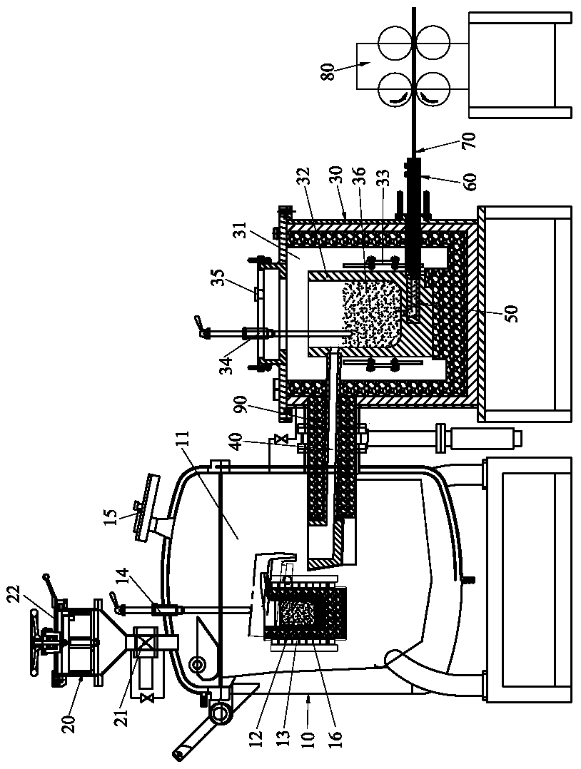
[0071] In this embodiment, a copper alloy vacuum continuous melting and casting device is composed of a vacuum melting chamber 10, a continuous vacuum feeding chamber 20, a vacuum casting chamber 30, an upper launder 40, a lower launder 50, a crystallizer 60, a dummy head 70, and a tractor 80. composition. The device is used to prepare chromium-zirconium bronze with a chromium content of 0.7wt%, a zirconium content of 0.2wt%, and an ingot diameter of Φ30mm.

[0072] The melting crucible 12 in the vacuum melting chamber 10 has a volume of 150 kg, the casting crucible 32 in the vacuum casting chamber 30 has a volume of 150 kg, the heating element 33 is a silicon carbide rod, and the inclination angle of the upper launder 40 is 10°. The melting and casting method includes the following steps:

[0073] (1) Assemble the above-mentioned copper alloy vacuum continuous melting and casting device, the melting thermocouple 14 and the casting thermocouple 34 are moved up to a position c...

Embodiment 2

[0086] In this embodiment, a copper alloy vacuum continuous melting and casting device is composed of a vacuum melting chamber 10, a continuous vacuum feeding chamber 20, a vacuum casting chamber 30, an upper launder 40, a lower launder 50, a crystallizer 60, a dummy head 70, and a tractor 80. composition. The device is used to prepare a B30 white copper tube billet with a nickel content of 30wt%, an ingot outer diameter of Φ20mm, and a wall thickness of 4mm.

[0087] The melting crucible 12 in the vacuum melting chamber 10 has a volume of 50 kilograms, the casting crucible 32 in the vacuum casting chamber 30 has a volume of 50 kilograms, the heating element 33 is a silicon carbide rod, and the inclination angle of the upper launder 40 is 10°. The melting and casting method includes the following steps:

[0088] (1) Assemble the above-mentioned copper alloy vacuum continuous melting and casting device, the melting thermocouple 14 and the casting thermocouple 34 are moved up t...


PUM

PropertyMeasurementUnit
diameteraaaaaaaaaa

Abstract

The invention discloses a copper alloy vacuum continuous smelting casting device. The copper alloy vacuum continuous smelting casting device includes a vacuum smelting chamber, a continuous vacuum feeding chamber, a vacuum casting chamber, an upper flow groove, a lower flow groove, a crystallizer, a dummy bar head and a traction machine. The vacuum smelting chamber is provided with a smelting cavity. The smelting cavity is internally provided with a smelting crucible capable of being tilted and returning to the origin. An induction coil is arranged on the melting crucible. The vacuum casting chamber is provided with a casting cavity. A casting crucible is arranged in the casting cavity. The outer side surface of the casting crucible is provided with a heating element. According to the copper alloy vacuum continuous smelting casting device, through matching and using of the vacuum melting chamber, the continuous vacuum feeding chamber, the vacuum casting chamber, the upper flow groove,the lower flow groove, the crystallizer, the dummy bar head and the traction machine, vacuum continuous feeding, continuous smelting and continuous casting are achieved, easily-oxidized metal can be smelted, the stability of alloy texture is ensured, degassing and refining can be conducted on a melt body through vacuum degree adjustment, and the service lives of parts such as the crucible and theflow grooves can be prolonged.

Description

technical field [0001] The invention relates to the technology in the field of copper alloy casting, in particular to a copper alloy vacuum continuous melting and casting device. Background technique [0002] At present, the ingot production methods of copper and copper alloys are mainly up-drawing, horizontal continuous casting and vertical down-drawing casting under atmospheric smelting. Since this type of production method is under non-vacuum atmospheric conditions, it is easy to realize uninterrupted feeding. , smelting and casting to achieve continuous preparation of ingots. However, because it is a non-vacuum system, when some refractory and easy-to-oxidize copper alloys are processed, due to reasons such as oxidation, gas absorption, and large amount of slag, it will cause a large amount of burning loss of elements and deterioration of casting conditions, which cannot guarantee alloy melting. Due to the stability of the body composition, qualified ingots cannot be pr...

Claims


Application Information

Patent Timeline
Patent Type & Authority Patents(China)
IPC IPC(8): B22D11/14B22D11/00B22D11/113B22D11/11B22D11/115B22D11/103
CPCB22D11/004B22D11/103B22D11/11B22D11/113B22D11/115B22D11/143
Inventor 杨斌李明茂陈辉明梅军张乐清
Owner JIANGXI UNIV OF SCI & TECH
Learn More