A full-length thermal insulation pipe with inner pipe direct connection

A thermal insulation and direct connection technology, applied in the direction of drilling pipe, casing, wellbore/well components, etc., can solve the problems of small heat conduction resistance, unsafety, heat loss reduction, etc., to save energy and improve heat preservation Effect, the effect of improving steam injection efficiency

Active Publication Date: 2019-11-15
SHENGLI OILFIELD SHENGJI PETROLEUM EQUIP
View PDF3 Cites 0 Cited by
  • Summary
  • Abstract
  • Description
  • Claims
  • Application Information

AI Technical Summary

Problems solved by technology

At present, in the ordinary heat-insulated oil pipe structure, there is no vacuum insulation layer at the joint of the coupling, and its own thermal conductivity is small, and the radial heat loss is much greater than that of other parts of the heat-insulated oil pipe. After calculation, the heat loss at the coupling accounts for about 70% of the heat loss in the whole length has become the main reason affecting the heat insulation effect of the heat insulation tube. At the same time, this part of the area has the largest thermal stress, and it is most likely to form an unsafe area after repeated steam stimulation operations.
In order to solve this problem, some domestic enterprises have developed direct-connection heat insulation pipes to replace ordinary heat insulation pipes, which have improved the structure of threaded joints, and improved connection strength and compression resistance. The buckle connection part of the pipe is still not covered with the insulation layer, although the heat loss has been reduced, but the effect is not ideal

Method used


Image

  • A full-length thermal insulation pipe with inner pipe direct connection
  • A full-length thermal insulation pipe with inner pipe direct connection

Examples


Embodiment Construction

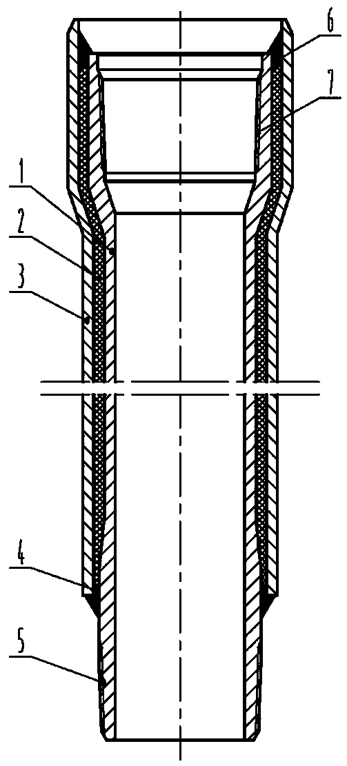
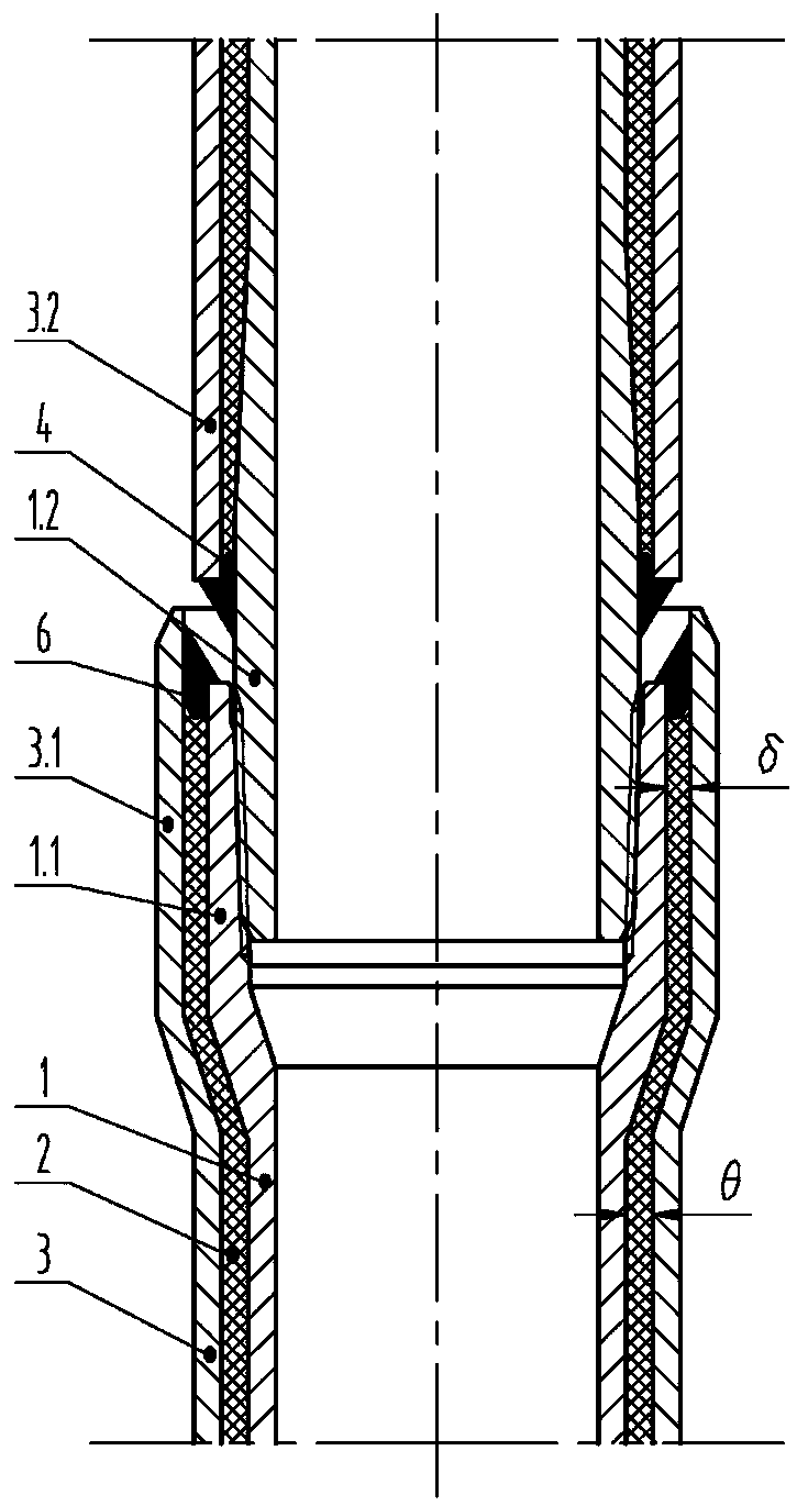
[0008] The present invention is described in detail below in conjunction with accompanying drawing: it comprises inner pipe 1, insulation layer 2, outer pipe 3, inner thread 7, outer thread 5, and one end of inner pipe 1 processes inner thread 7, and the other end processes outer thread 5, inner The inner pipe 1.1 at the threaded end is directly connected to the inner pipe 1.2 at the outer threaded end of another heat-insulating pipe; The diameter is 10-16mm larger than the thickened outer diameter of the 1.2 end of the inner tube at the external thread end, and the outer diameter of the 3.1 end of the outer tube at the inner thread end is flared, and the gap between the inner diameter of the flared part and the outer diameter of the 1.1 thickened end of the inner tube at the female thread end is δ , the thickness of the thermal insulation layer between the inner tube 1 and the outer tube 3 is θ, and its δ≈θ, and the thermal insulation layer is also wrapped in the annular space...


PUM


Abstract

The invention discloses an inner pipe direct connection type full-length heat preservation and heat insulation pipe especially suitable for thick oil recovery in an oil field. The inner pipe direct connection type full-length heat preservation and heat insulation pipe comprises an inner pipe body, a heat preservation layer, an outer pipe body, an inner thread and an outer thread; the inner threadis machined at one end of the inner pipe body, and the outer thread is machined at the other end of the inner pipe body; the inner thread end of the inner pipe body is directly connected with the outer thread end of the inner pipe body of another heat insulation pipe; the end of the outer thread end of the inner pipe main body is thickened ordinarily, the end of the inner thread end of the inner pipe main body is thickened, and the thickened outer diameter of the end of the inner thread end of the inner pipe main body is 10-16 mm larger than that of the end of the outer thread end of the innerpipe main body; the end of an inner thread end of the outer pipe main body is flared, the clearance between the inner diameter of the flared position and the outer diameter of the thickened end of the inner thread end of the inner pipe main body is delta, the thickness of the heat preservation layer between the inner pipe body and the outer pipe body is theta, and delta is approximately equal totheta; and the heat preservation layer is also wound in an annular space at the thickened position of the inner thread end of the inner pipe body and the flared position of the inner thread end of theouter pipe body. The heat preservation layer is wound in the annular spacebetween the outer pipe body and the inner pipe body in a full-length mode, so that a large amount of heat loss in the connection position of the heat insulation pipes is avoided, and the heat preservation effect of the heat insulation pipe is improved by a large margin.

Description

technical field [0001] The invention relates to a full-length heat-preservation and heat-insulation pipe with direct connection of inner pipes, which is especially suitable for heavy oil exploitation in oilfields. Background technique [0002] Insulated tubing is an important equipment for steam injection to exploit oil. It can reduce heat loss during steam injection, improve steam injection and oil recovery efficiency, and protect oil well casing and cement sheath from thermal stress damage. At present, in the ordinary heat-insulated oil pipe structure, there is no vacuum insulation layer at the joint of the coupling, and its own thermal conductivity is small, and the radial heat loss is much greater than that of other parts of the heat-insulated oil pipe. After calculation, the heat loss at the coupling accounts for about 70% of the total length heat loss has become the main reason affecting the heat insulation effect of the heat insulation pipe. At the same time, this par...

Claims


Application Information

Patent Timeline
Patent Type & Authority Patents(China)
IPC IPC(8): E21B17/00E21B43/24
CPCE21B17/00E21B43/24
Inventor 张喜庆杨松筠杜韧之宫树战张兴华蔡文革杨成玉贾武江杜春伟郝悦
Owner SHENGLI OILFIELD SHENGJI PETROLEUM EQUIP
Why Eureka
Try Eureka