Friction performance detection device of brake device and friction coefficient calculation method

A friction performance and detection device technology, which is applied in the field of brake friction, can solve the problems of shortened lost motion time, high cost of the bench, insufficient detection of brake performance, etc., and achieves the effect of simple structure, comprehensive detection and convenient portability

Active Publication Date: 2018-03-13
徐州市质量技术监督综合检验检测中心 +1
View PDF14 Cites 5 Cited by
  • Summary
  • Abstract
  • Description
  • Claims
  • Application Information

AI Technical Summary

Problems solved by technology

[0003] For a long time, people's research on electrohydraulic drum brakes has mainly focused on structural parameter design, brake shoe clearance adjustment, and shortening of lost motion time, but the detection of brake performance is not sufficient.
For example: the utility model patent with the patent number ZL201220150282.X designs a test bench for testing the performance of electrohydraulic brakes, but the bench test is expensive and cannot be carried out at the working site; the patent application number 201420740657.7 proposes an electrohydraulic Brake real-time monitoring device, but the patent only designed a device for alarming when the brake fails, and did not explain the method of judging the brake failure
[0004] Judging from the current research status in related disciplines, great progress has been made in the structural design of electrohydraulic drum brakes, installation parameter adjustment and inertia simulation braking tests, but the friction performance of electrohydraulic drum brakes in the field Insufficient research on detection

Method used


Image

  • Friction performance detection device of brake device and friction coefficient calculation method
  • Friction performance detection device of brake device and friction coefficient calculation method
  • Friction performance detection device of brake device and friction coefficient calculation method

Examples


Embodiment Construction

[0020] The present invention will be further described below in conjunction with accompanying drawing.

[0021] The following will clearly and completely describe the technical solutions in the embodiments of the present invention with reference to the accompanying drawings in the embodiments of the present invention. Obviously, the described embodiments are only some, not all, embodiments of the present invention. Based on the embodiments of the present invention, all other embodiments obtained by persons of ordinary skill in the art without making creative efforts belong to the protection scope of the present invention.

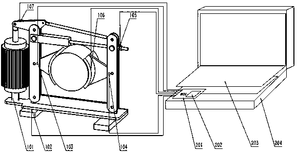
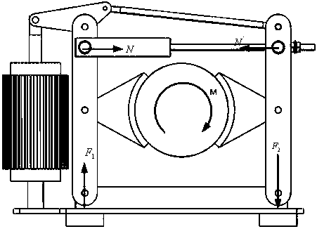
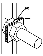
[0022] Such as figure 1 As shown, the present invention includes an electrohydraulic drum brake 101, a first pressure sensor 102, two first displacement sensors 103, 104, a second pressure sensor 105, a temperature sensor 106, a second displacement sensor 107 and a single-chip microcomputer 201;

[0023] The first pressure sensor 102 is arranged at the bot...


PUM


Abstract

The invention discloses a friction performance detection device of a brake device and a friction coefficient calculation method. The detection device comprises a pressure sensor, a displacement sensor, a temperature sensor and a single-chip microcontroller. According to the definition of a friction coefficient, mu=F / N; the N expresses a braking pressure that is a spring force provided by a brakingspring and is obtained by detection of a second pressure sensor; the F expresses a braking force that is obtained by conversion of an overturning moment of a floor by an electro-hydraulic drum type braking device pedestal; according to a formula: F=F1d / D, the F1 expresses a braking moment that is measured by a first pressure sensor, the d expresses a distance between a left pedestal and a right pedestal of the electro-hydraulic drum type braking device, and the D expresses a distance between two application points; and thus mu=F1d / DN. According to the invention, with conversion processing bythe pressure sensor, the temperature sensor, the displacement sensor and the single-chip microcomputer, changes of the friction coefficient of the braking device and the temperature are detected; andmeanwhile, a push rod travel of an electro-hydraulic drum type braking device and a back distance of a friction piece are measured by the displacement sensor, so that the friction coefficient of the braking device is detected in real time.

Description

technical field [0001] The invention relates to a brake friction performance detection device and a friction coefficient calculation method, belonging to the technical field of brake friction. Background technique [0002] Electro-hydraulic drum brakes have high braking efficiency and are widely used in large-scale load-carrying equipment such as cranes and belt conveyors. They are important components necessary for speed and position adjustment and reliable stopping. Cooperate, two symmetrically arranged brake shoes radially hold the brake wheel to generate braking torque: when the brake is opened, the electrohydraulic pusher generates thrust to compress the spring, and the brake shoe releases the brake disc; when the brake is closed, the pusher Unloading, the brake shoes hold the brake disc tightly under the action of the brake spring force to generate braking. [0003] For a long time, people's research on electrohydraulic drum brakes has mainly focused on the design of ...

Claims


Application Information

Patent Timeline
IPC IPC(8): G01M13/00G01N19/02
CPCG01M13/00G01N19/02
Inventor 王宁鲍久圣翟羽阴妍马驰刘同冈卜凡纬孙峰
Owner 徐州市质量技术监督综合检验检测中心
Why Eureka
Try Eureka