
Combined type locking washer

A locking washer, combined technology, applied in the direction of washers, locking fasteners, threaded fasteners, etc., can solve the problems of damaged threads on the surface of the screw, easy to be crushed, frequent use, etc., to prevent Sliding phenomenon, the effect of preventing up and down vibration and lateral translation, and improving its own strength

Inactive Publication Date: 2018-03-13
响水县冠龙轴承座制造有限公司
View PDF0 Cites 0 Cited by
  • Summary
  • Abstract
  • Description
  • Claims
  • Application Information

AI Technical Summary

Problems solved by technology

[0002] The washer refers to the part between the connected part and the nut, generally a flat metal ring, which is used to protect the surface of the connected part from being scratched by the nut and disperse the pressure of the nut on the connected part. The lock washer is composed of A plurality of rubber rings or metal rings are bonded and vulcanized as a whole. It is used to seal the sealing ring of the thread and flange connection. The ring includes a metal ring and a rubber gasket. The combined sealing gasket can be divided into A according to the structure. Type B and Type B, washers are frequently used in mechanical connections. They are usually placed between the nut and the connected parts to prevent the nut from loosening during use. The upper and lower ends of the existing washers are mostly It is a smooth plane. The friction between this smooth plane and the nut and the connected parts is very small. When the nut is subjected to strong vibration, the nut is easy to loosen. The locking washer has a better anti-loosening effect, but the washer The strength itself is not high, and it is easy to be crushed, and the vibration sideways movement between the washer and the surface of the screw will damage the thread on the surface of the screw, resulting in the phenomenon of slipping

Method used


Image

  • Combined type locking washer
  • Combined type locking washer

Examples


Embodiment Construction

[0015] The following will clearly and completely describe the technical solutions in the embodiments of the present invention with reference to the accompanying drawings in the embodiments of the present invention. Obviously, the described embodiments are only some, not all, embodiments of the present invention.

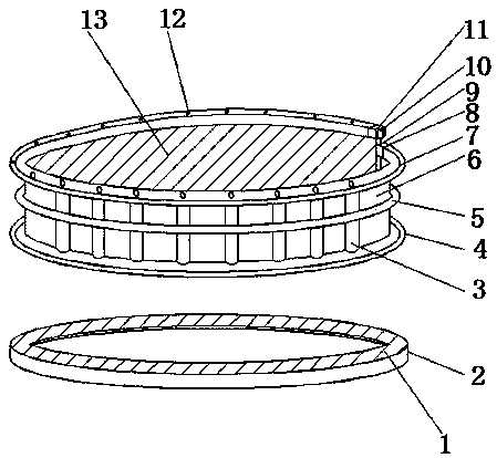
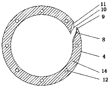
[0016] refer to figure 1 and figure 2 , a combined locking washer, including a clamping washer 2 and a support ring 6 fixed on the outer wall of the screw rod, the outer wall of the top of the clamping washer 2 is provided with a first locking pattern 1, and the outer wall of the top of the support ring 6 is welded with an upper gasket 7. The outer wall of the bottom of the support ring 6 is welded with the lower gasket 4, the outer wall of the bottom of the lower gasket 4 is provided with a second card pattern 14, and the outer wall of the top of the upper gasket 7 and the outer wall of the bottom of the lower gasket 4 are welded with bumps 12, The inner wall of o...


PUM


Abstract

The invention discloses a combined locking washer, which comprises a clamping washer and a support ring fixed on the outer wall of a screw rod, the top outer wall of the clamping washer is provided with a first locking thread, and the top outer wall of the support ring is welded with an upper Gasket, and the outer wall of the bottom of the support ring is welded with a lower gasket, the outer wall of the bottom of the lower gasket is provided with a second card pattern, and the outer wall of the top of the upper gasket and the outer wall of the bottom of the lower gasket are welded with bumps, the upper gasket A first alloy joint is welded on the inner wall of one side of the sheet, and a locking groove is formed on the side away from the protrusion of the first alloy joint. The invention cooperates with the clamping gasket and the threaded gasket to prevent up and down vibration and lateral translation, so that the gasket can play a locking role, and the vertical reinforcing rib and the annular clamping ring can improve their own strength and will not be crushed. The clamping fit of the piece prevents the phenomenon of slipping when the bolt is tightened, and locks the entire bolt structure. The high-strength clamping block of the alloy joint cooperates, and there will be no sideways movement or breakage.

Description

technical field [0001] The invention relates to the technical field of locking washers, in particular to a combined locking washer. Background technique [0002] The washer refers to the part between the connected part and the nut, generally a flat metal ring, which is used to protect the surface of the connected part from being scratched by the nut and disperse the pressure of the nut on the connected part. The lock washer is composed of A plurality of rubber rings or metal rings are bonded and vulcanized as a whole. It is used to seal the sealing ring of the thread and flange connection. The ring includes a metal ring and a rubber gasket. The combined sealing gasket can be divided into A according to the structure. Type B and Type B, washers are frequently used in mechanical connections. They are usually placed between the nut and the connected parts to prevent the nut from loosening during use. The upper and lower ends of the existing washers are mostly It is a smooth pl...

Claims


Application Information

Patent Timeline
Patent Type & Authority Applications(China)
IPC IPC(8): F16B43/00F16B39/24
CPCF16B43/00F16B39/24
Inventor 杨燕燕
Owner 响水县冠龙轴承座制造有限公司
Learn More