Self-compensating, locking and quick-connecting high-pressure pipe connector

A self-compensating, high-pressure pipe technology, applied to pipes/pipe joints/fittings, expansion compensation devices for pipelines, pipe components, etc., can solve problems such as unfavorable energy saving and emission reduction, poor practicability, and increased manufacturing costs, and achieve shortening The installation period, the sealing effect is good, and the effect of improving economic benefits

Inactive Publication Date: 2010-07-14
王甲南
View PDF6 Cites 5 Cited by
  • Summary
  • Abstract
  • Description
  • Claims
  • Application Information

AI Technical Summary

Problems solved by technology

But its shortcomings are: today's world has ushered in the era of high energy efficiency and low carbon economy. The 2009 United Nations Climate Change World Conference Framework Convention requires the governments of all countries and the Chinese government to commit to require more development and use of high-tech, high-energy-efficiency and low-efficiency energy-saving and emission-reducing products. Carbon-friendly technology products, but there are many parts in the structural design, and the left and right sets need to be manufactured using two sets of precision casting molds, which increases the manufacturing cost and is not conducive to energy saving and emission reduction. It is produced in a low-cost, mass-produced, high-energy-efficiency, low-carbon economy Promoted applications, poor practicability

Method used


Image

  • Self-compensating, locking and quick-connecting high-pressure pipe connector
  • Self-compensating, locking and quick-connecting high-pressure pipe connector
  • Self-compensating, locking and quick-connecting high-pressure pipe connector

Examples


Embodiment Construction

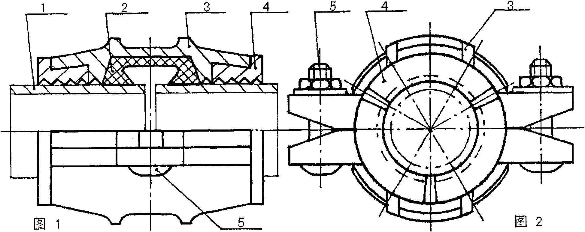
[0038] The present invention is described in further detail below in conjunction with accompanying drawing and embodiment thereof:

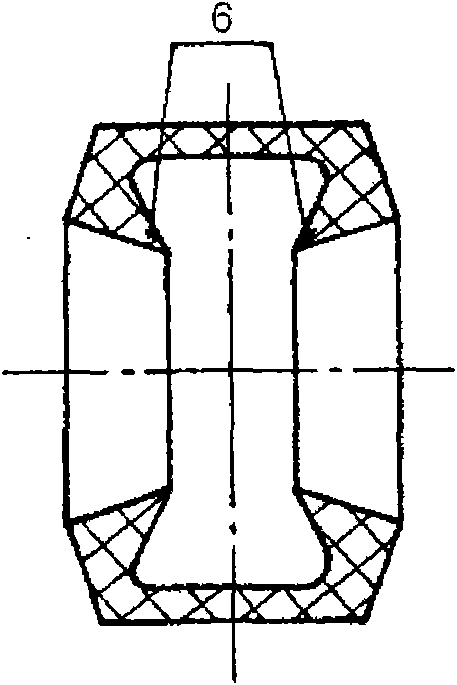
[0039] figure 1 , 2 The overall structure of the self-compensating lockable quick-connect high-pressure pipe joint of the present invention is shown. It is characterized in that the rubber sealing sleeve 2 surrounds the outer circle of the pipe fitting 1, the rubber sealing sleeve 2 is provided with an angle ring 6 with an open inner cavity, and is placed on the outer wall of the nozzle of the two pipe fittings, and the trapezoidal boss provided on the clamp 3 8 is coordinated with the trapezoidal groove 9 provided on the clamp 3 and fastened symmetrically on the pipe fitting 1, and pressed against the outer surface of the rubber sealing sleeve 2. The inner circular surface of the clamp 3 is provided with a circular tine 10 and They are respectively pasted on the outer walls of the pipe fittings 1 with the same arc. Three groups of claws 4 ar...


PUM


Abstract

The invention relates to a self-compensating, locking and quick-connecting high-pressure pipe connector, which consists of a rubber sealing sleeve 2, a clamp hoop 3, a clamp claw 4 and a fastening component 5 and overcomes the defects of the existing pipe connection technology such as high cost and poor practicality. The self-compensating, locking and quick-connecting high-pressure pipe connector is characterized in that the rubber sealing sleeve 2 surrounds the excircle of a pipe, the angular ring of the open cavity of the rubber sealing sleeve 2 is arranged on two pipes. The clamp hoop 3 is symmetrically buckled with the pipe and is pressed on the outer surface of the rubber sealing sleeve 2, the upper annular pointed teeth of the clamp hoop 3 are adhered to the pipe, the inner arc-shaped surface of the clamp claw 4 is provided with a plurality of annular pointed teeth and is arranged in the inner conical groove of the clamp hoop 3, and the clamp claw 4 is adhered to the outer wall of the pipe and can slide along the axial direction of the pipe to concentrically contract, buckle and lock the pipe. The high-pressure pipe connector can resist high, medium and low pressure, and adopts no welding, no flange, no groove, no electric thermal fusion welding or no external compensator, and has the functions of self compensation, locking, all-round safe sealing due to integration of rigid and flexible features, and labor and time conservation. Particularly under harsh environmental conditions, the high-pressure pipe connector has the advantages of convenient and rapid connection, low cost, high efficiency, energy conservation, emission reduction and environmental protection. The invention can be used for connecting two pipes for fluid transmission.

Description

technical field [0001] The invention relates to a high-pressure pipe joint for butt-connecting two pipe fittings intended to convey fluid, in particular to a self-compensating, lockable, rigid-flexible, all-round safety-sealed self-compensating joint for the connected pipe fittings. Lockable quick-connect high-pressure pipe joints. Background technique [0002] According to the investigation, the original traditional welding method, flange method and grooved pipe joint are used in the large-caliber high, medium and low pressure pipe joint technology for conveying fluid in the world today. These pipe connection technologies, when steel flanges and pipelines, pipelines and pipelines are arc welded, or rolled and grooved, there are external and internal anti-corrosion layers that will damage the steel pipes, and secondary anti-corrosion operations are required. The welded flange pipe connection technology of the steel pipeline system requires flaw detection to prevent false we...

Claims


Application Information

Patent Timeline
IPC IPC(8): F16L51/00F16L55/17
Inventor 王甲南
Owner 王甲南
Why Eureka
Try Eureka