
Circularly polarized antenna

A circularly polarized antenna, circularly polarized technology, applied to antennas, resonant antennas, electrical components, etc., can solve the problems of large volume, narrow bandwidth, complex feed network, etc. Effects of Bandwidth, High Gain Characteristics

Active Publication Date: 2018-03-06
香港城市大学深圳研究院
View PDF1 Cites 5 Cited by
  • Summary
  • Abstract
  • Description
  • Claims
  • Application Information

AI Technical Summary

Problems solved by technology

However, this technology requires a relatively complex feed network, which is very difficult to implement in the millimeter wave band.
The second method is to use a single feed method, such as a circularly polarized angle-cut patch antenna. This antenna has a simple structure and is easy to implement, but its bandwidth is very narrow and it is not suitable for wide-band applications.
However, the volume of the horn antenna is relatively large and the height is relatively high.
It is not suitable for some application scenarios
Moreover, the methods mentioned above are difficult to realize the function of beam scanning

Method used


Image

  • Circularly polarized antenna
  • Circularly polarized antenna
  • Circularly polarized antenna

Examples


Embodiment Construction

[0051] In order to have a clearer understanding of the technical features, purposes and effects of the present invention, the specific implementation manners of the present invention will now be described with reference to the accompanying drawings.

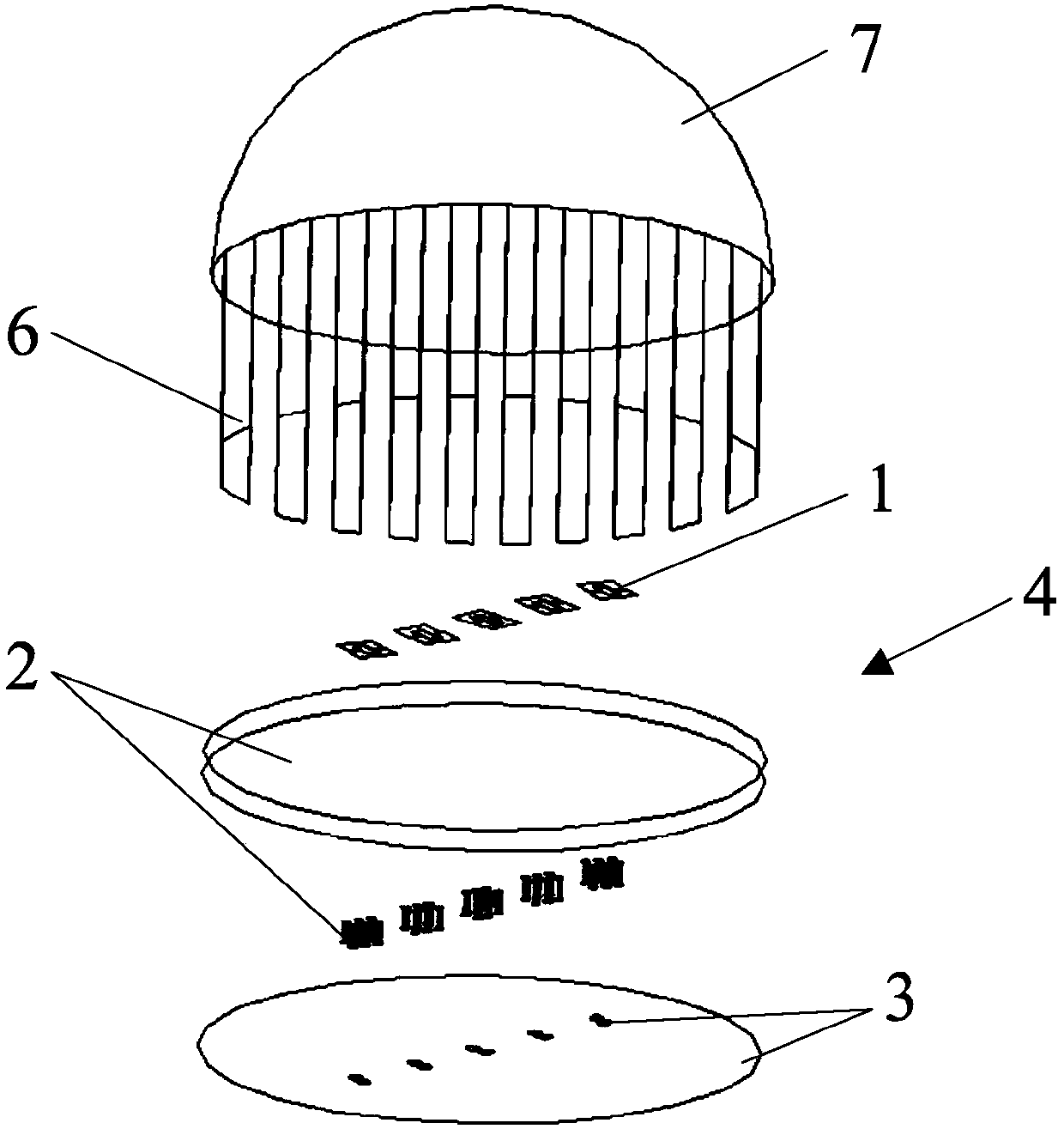
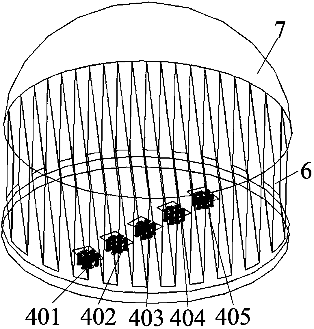
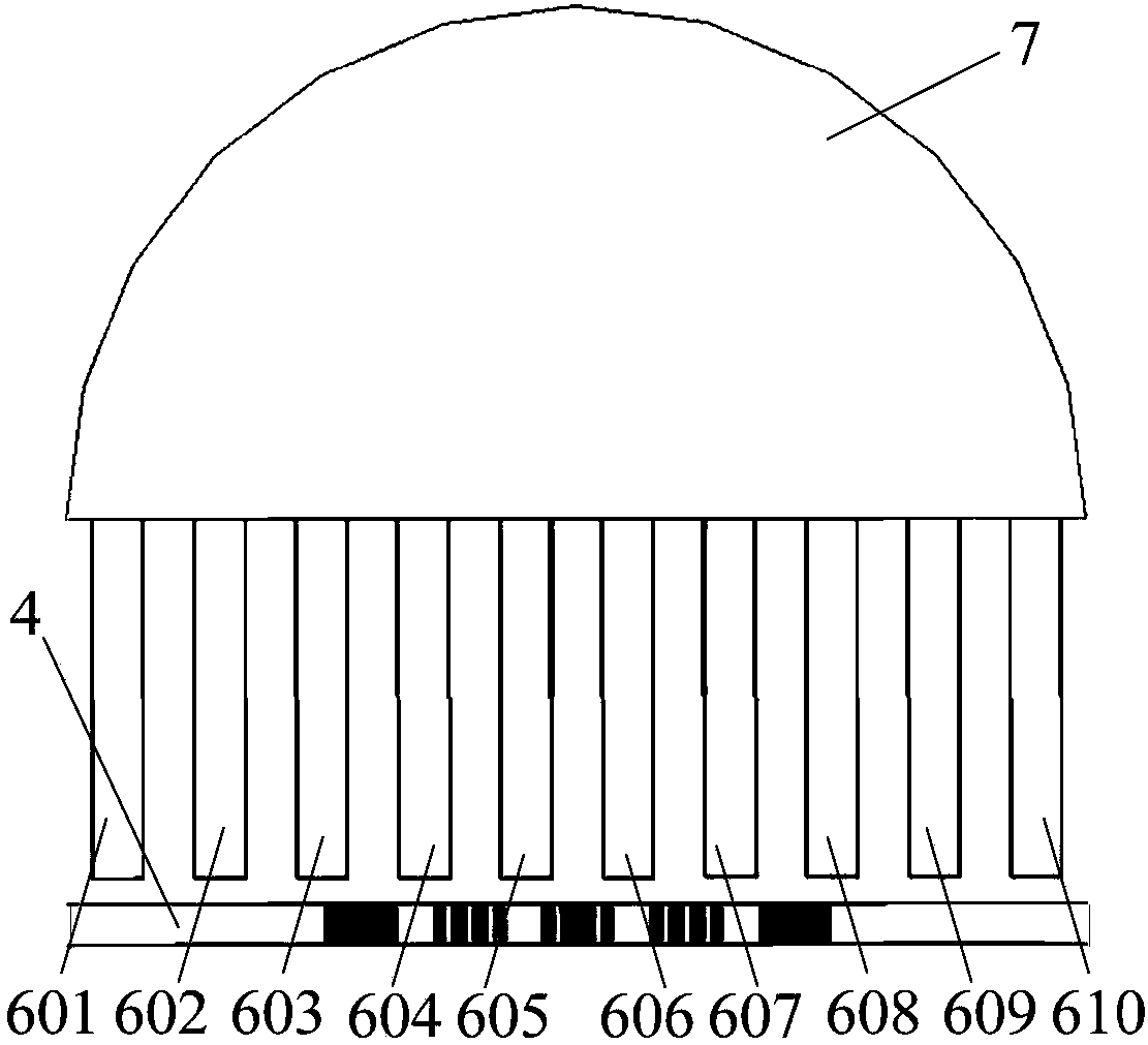
[0052] Such as figure 1 , figure 2 , image 3 As shown, the present invention provides a circularly polarized antenna, which can be used to receive and transmit various types of electromagnetic waves, and is especially suitable for receiving and transmitting millimeter waves that require high antenna gain, so it can also be called millimeter wave circular polarization. The antenna comprises a linearly polarized antenna source 4 and a circularly polarized lens for radiating linearly polarized waves, and the circularly polarized lens includes a circular polarizer 6 for converting linearly polarized waves into circularly polarized waves and using A dielectric lens 7 that refracts and converges circularly polarized waves, the circul...


PUM


Abstract

The invention provides a circularly polarized antenna comprising a linearly polarized antenna source, a circularly polarized lens and a medium lens, wherein the linearly polarized antenna source is used for radiating linearly polarized waves; the circularly polarized lens includes a circular polarization device which is located above the linearly polarized antenna source and used for converting the linearly polarized waves into circularly polarized waves, the circular polarization device comprises a plurality of dielectric grids which are vertically and parallelly arranged, the plurality of dielectric grids are arranged in sequence along the horizontal direction at equal intervals; and the medium lens is connected above the circular polarization device and is used for refracting and converging the circularly polarized waves. The antenna can be used for 5G mobile communication, so that the wider axial ratio bandwidth is achieved, meanwhile, the gain of the antenna is improved, moreover,the wave beam scanning of the antenna is realized, and the antenna is suitable for the scene of mobile communication such as the fifth generation in the future.

Description

technical field [0001] The invention relates to the field of wireless mobile communication, in particular to a high-gain circularly polarized antenna. Background technique [0002] The antenna is an energy conversion device for receiving and sending electromagnetic waves in a wireless communication system, and is an indispensable part of a wireless mobile communication system. With the development of wireless mobile communication technology, the requirements for data transmission rate are getting higher and higher. The millimeter wave frequency band has a communication bandwidth of 7GHz without a license, which can greatly increase the rate of wireless communication and realize the instant transmission of large amounts of data. Since the higher the frequency, the greater the loss of the signal during transmission, which puts forward a higher index for the gain of the antenna. On the other hand, in the millimeter wave band, the antenna is small in size and difficult to proc...

Claims


Application Information

Patent Timeline
Patent Type & Authority Applications(China)
IPC IPC(8): H01Q15/24H01Q9/04
Inventor 黄衡王凯旭
Owner 香港城市大学深圳研究院
Learn More