Differential circulating fluidized bed catalytic pyrolysis gasification apparatus and differential circulating fluidized bed catalytic pyrolysis gasification method

A circulating fluidized bed, pyrolysis gasification technology, applied in the field of coal gasification, can solve the problems of poor operation stability, low carbon conversion rate and gasification intensity, low methane yield, etc., and achieves reduced load and high gasification intensity. , the effect of high energy utilization

Active Publication Date: 2018-03-06
CHINA PETROLEUM & CHEM CORP +1
View PDF8 Cites 0 Cited by
  • Summary
  • Abstract
  • Description
  • Claims
  • Application Information

AI Technical Summary

Problems solved by technology

[0008] One of the technical problems mainly solved by the present invention is the problems of low carbon conversion rate and gasification intensity, low methane yield and poor operation stability of the device in the prior art. The present invention proposes a differential circulating fluidized bed catalytic pyrolysis gas The device is composed of a fast fluidized bed and a slow fluidized bed. The carbon-containing raw material undergoes catalytic pyrolysis, tar decomposition and methanation reactions in the fast fluidized bed, and the coal char particles produced are in the slow fluidized bed. The catalytic gasification reaction is carried out in the medium, which improves the carbon conversion rate and methane yield, and the device operates stably and is easy to scale up

Method used


Image

  • Differential circulating fluidized bed catalytic pyrolysis gasification apparatus and differential circulating fluidized bed catalytic pyrolysis gasification method
  • Differential circulating fluidized bed catalytic pyrolysis gasification apparatus and differential circulating fluidized bed catalytic pyrolysis gasification method
  • Differential circulating fluidized bed catalytic pyrolysis gasification apparatus and differential circulating fluidized bed catalytic pyrolysis gasification method

Examples


Embodiment 1

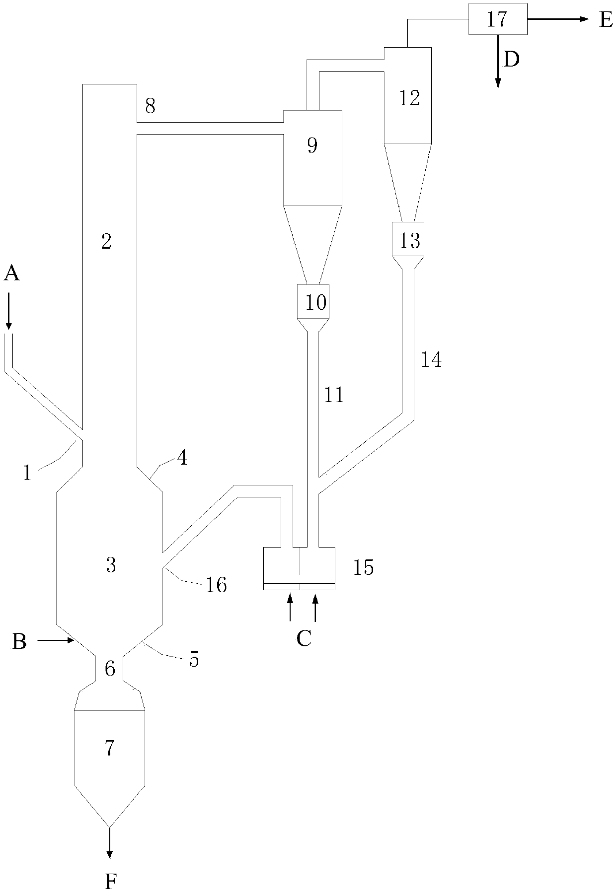
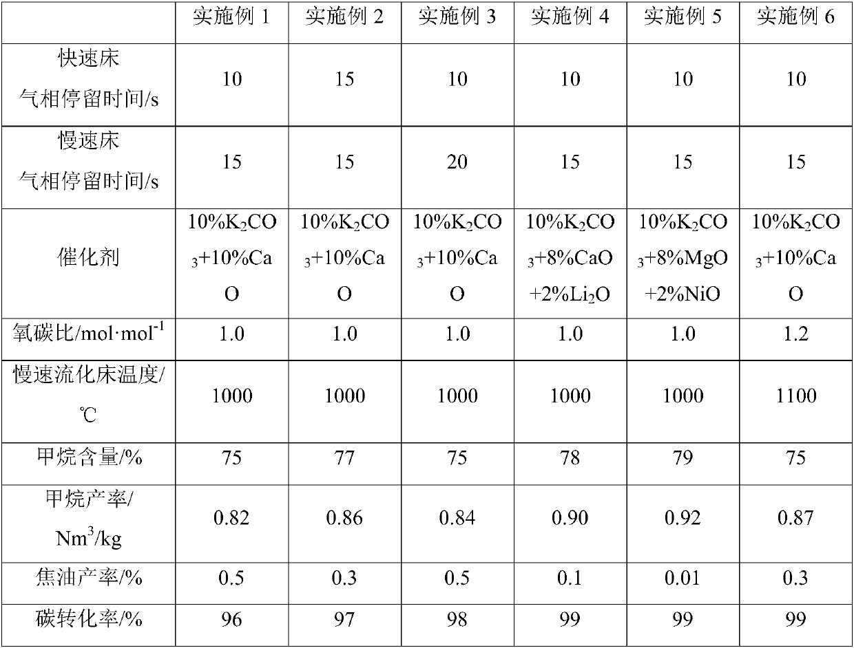
[0046] A differential circulating fluidized bed catalytic pyrolysis gasification reaction device, the inner diameter of the fast fluidized bed is 0.2m, the linear velocity is 2m / s, the gas phase residence time is 10s, the inner diameter of the slow fluidized bed is 0.5m, and the linear velocity is 0.2m / s , the gas phase residence time is 15s, the raw material inlet is located at 1 / 8 of the height of the fast fluidized bed, the angle between the constriction and the horizontal axis is 45°, the angle between the inclined surface of the gas distributor and the horizontal axis is 30°, the conical surface of the gas distributor There are 10 circles of pores on the top, the opening rate is 1.5%, and the inner diameter of the lower slag opening is 0.2m.

[0047] In the experiment, Inner Mongolia lignite and 10% K 2 CO 3 +10%CaO catalyst mixed, fed into the fast fluidized bed from the raw material inlet, mixed and contacted with the high-temperature synthesis gas from the necking, to...

Embodiment 2

[0049] A differential circulating fluidized bed catalytic pyrolysis gasification reaction device, the inner diameter of the fast fluidized bed is 0.2m, the linear velocity is 2m / s, the gas phase residence time is 15s, the inner diameter of the slow fluidized bed is 0.5m, and the linear velocity is 0.2m / s , the gas phase residence time is 15s, the raw material inlet is located at 1 / 8 of the height of the fast fluidized bed, the angle between the constriction and the horizontal axis is 45°, the angle between the inclined surface of the gas distributor and the horizontal axis is 30°, the conical surface of the gas distributor There are 10 circles of pores on the top, the opening rate is 1.5%, and the inner diameter of the lower slag opening is 0.2m.

[0050] In the experiment, Inner Mongolia lignite and 10% K 2 CO 3 +10%CaO catalyst mixed, fed into the fast fluidized bed from the raw material inlet, mixed and contacted with the high-temperature synthesis gas from the necking, to...

Embodiment 3

[0052] A differential circulating fluidized bed catalytic pyrolysis gasification reaction device, the inner diameter of the fast fluidized bed is 0.2m, the linear velocity is 2m / s, the gas phase residence time is 10s, the inner diameter of the slow fluidized bed is 0.5m, and the linear velocity is 0.2m / s , the gas phase residence time is 20s, the raw material inlet is located at 1 / 8 of the height of the fast fluidized bed, the angle between the constriction and the horizontal axis is 45°, the angle between the inclined surface of the gas distributor and the horizontal axis is 30°, the conical surface of the gas distributor There are 10 circles of pores on the top, the opening rate is 1.5%, and the inner diameter of the lower slag opening is 0.2m.

[0053] In the experiment, Inner Mongolia lignite and 10% K 2 CO 3 +10%CaO catalyst mixed, fed into the fast fluidized bed from the raw material inlet, mixed with the high-temperature syngas from the shrinkage port, to carry out pyr...


PUM

PropertyMeasurementUnit
particle diameteraaaaaaaaaa

Abstract

The invention relates to a differential circulating fluidized bed catalytic pyrolysis gasification apparatus. A purpose of the present invention is to solve the problems of low carbon conversion rate,low methane yield, and poor operation stability and poor reliability of the gasification furnace in the prior art. According to the technical scheme of the present invention, a gasification apparatuscomprising a rapid fluidized bed and a slow fluidized bed is used, the rapid fluidized bed on the upper portion and the slow fluidized bed on the lower portion form necking connection, a raw materialinlet is positioned on the bottom portion of the rapid fluidized bed, and a return material inlet is positioned on the middle portion of the slow fluidized bed. The differential circulating fluidizedbed catalytic pyrolysis gasification mainly comprises that a catalyst-loading carbon-containing raw material is subjected to catalytic pyrolysis, tar decomposition and methanation reaction in the gasification section of the rapid fluidized bed to generate methanation-rich synthesis gas, the semi-coke particles obtained after the pyrolysis are collected and are cyclically introduced into the slowfluidized bed, and a combustion gasification reaction is performed. With the technical scheme of the present invention, the problems in the prior art are well solved. The apparatus and the method of the present invention can be used in the field of coal-to-gas.

Description

technical field [0001] The present invention relates to a coal catalytic pyrolysis and gasification reaction device and method, more specifically, the present invention designs a differential circulating fluidized bed catalytic pyrolysis gasification device and method, which belongs to the field of coal gasification. Background technique [0002] As my country's basic energy and important industrial raw materials, coal plays a vital role in my country's economic construction and development. In the next few decades, the coal-based energy structure will be difficult to change. However, the inefficient and rough utilization of coal will seriously affect the environmental problems, and affect the sustainable development of my country's national economy and the health of the people. As an important way of clean and efficient utilization of coal, coal gasification technology has been widely used in metallurgy, chemical industry, building materials, machinery and other industrial ...

Claims


Application Information

Patent Timeline
Patent Type & Authority Applications(China)
IPC IPC(8): C10J3/60C10J3/56C10J3/84
CPCC10J3/56C10J3/60C10J3/84C10J2300/1603Y02P20/52
Inventor 金渭龙顾松园钟思青金永明
Owner CHINA PETROLEUM & CHEM CORP
Why Eureka
Try Eureka