Drill coping device

A drill bit and drill bit fixture technology, which is used in drilling tool accessories, grinding workpiece supports, drilling/drilling equipment, etc., can solve the problems of damaged drill bits, excessive grinding, and high manufacturing costs, avoiding safety accidents and reducing The effect of low grinding amount and manufacturing cost

Pending Publication Date: 2018-03-06
赵建秋
View PDF9 Cites 1 Cited by
  • Summary
  • Abstract
  • Description
  • Claims
  • Application Information

AI Technical Summary

Problems solved by technology

The disadvantages of the existing drill bit grinding machine are: 1. Only for drill bits of a certain size range, such as small-size drill bit grinding machines cannot clamp large-size drill bits, and for large-size drill bit grinding machines, small-size drill bit clamps It is difficult to maintain, and it is difficult to guarantee the required accuracy; 2. The method of screw feeding and dial setting parameters is generally used. The above-mentioned method is cumbersome to operate, difficult for operators to master, and its volume is large, and the manufacturing cost is high; 3. Due to the use of screw feeding The sliding components driven by the screw are restricted by the screw feeding mechanism and cannot slide freely; 4. For large drill bit grinding machines, the drill bit is at an angle of lift during operation, and it is supported on the grinding wheel, while the rotation direction of the grinding wheel is the same as that of the drill bit. The upward direction is reversed. In the above situation, the grinding wheel will exert a downward force on the drill bit during grinding, so that the lift angle of the drill bit will decrease. The decrease of the drill bit lift angle will increase the grinding amount, and the downward force exerted by the grinding wheel will increase with the grinding amount. Increase and increase, because the sliding components cannot slide freely, thus forming a vicious circle, resulting in excessive grinding, in severe cases, the drill bit will be damaged, the grinding wheel will crack, causing a safety accident; complex and expensive

Method used


Image

  • Drill coping device
  • Drill coping device
  • Drill coping device

Examples


Embodiment Construction

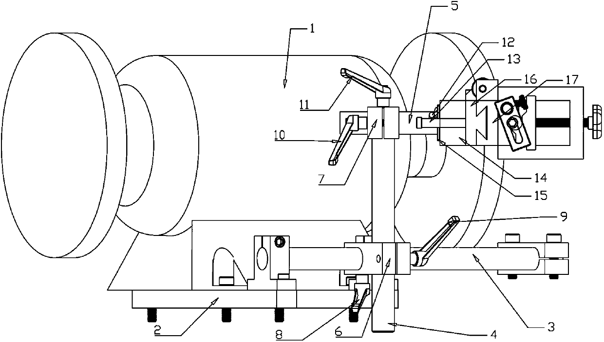
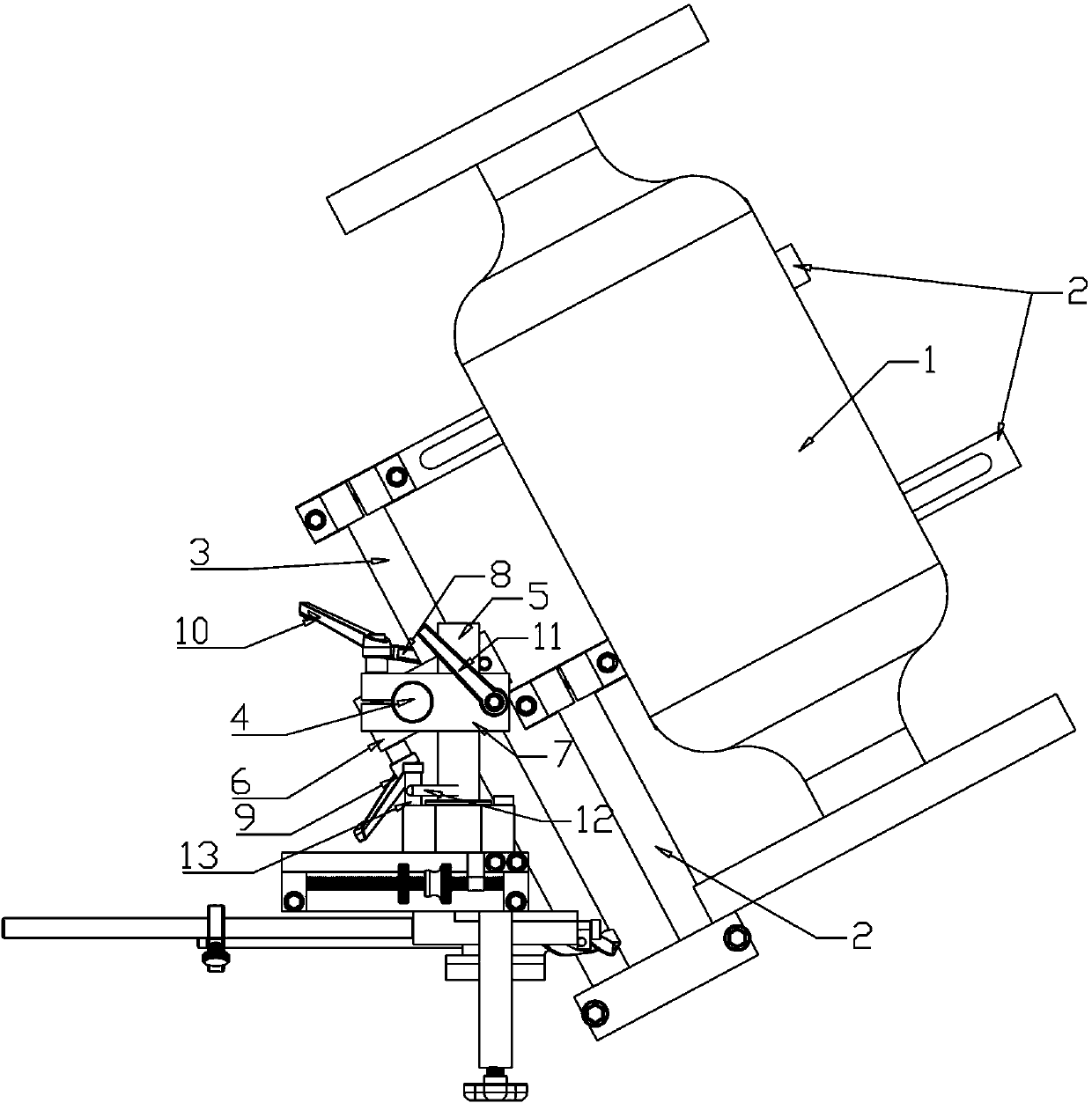
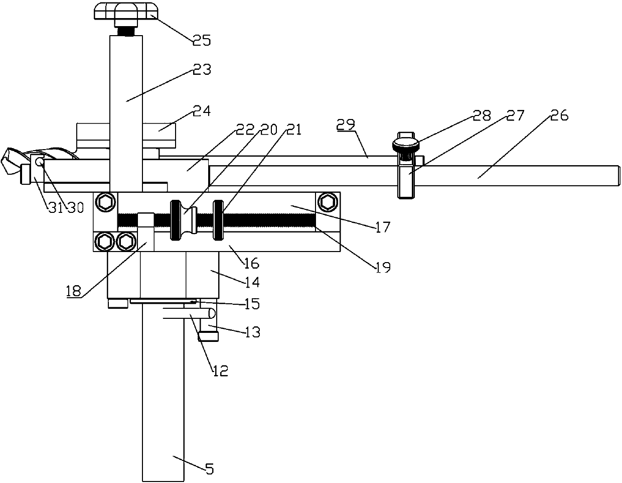
[0032] refer to Figure 1-12 As shown, the drill bit grinding device of the present invention comprises a bracket 2, a slide rail 3, a column 4, a main shaft 5, a slider assembly and a drill bit fixture. One end of the bracket 2 is connected to the grinder 1, and the opposite end is connected to the slide rail 3. The slide rail 3, the column 4 and the main shaft 5 are respectively connected by connecting blocks. The connecting blocks are provided with fasteners. By adjusting the tightness of the fasteners, the slide rail 3, the column 4 and the main shaft 5 are connected The relative position can be adjusted between them, the main shaft 5 is connected through the bearing 15, the bearing seat 14 and the slider base 16 in the slider assembly, the drill bit fixture is fixed on the slider 17 in the slider assembly, and follows the The slider assembly rotates. The connecting block is preferably a cross connecting block (the connecting block has a cross-shaped mounting hole), and t...


PUM


Abstract

The invention discloses a drill coping device. The drill coping device mainly comprises a support, a slide rail, an upright, a main shaft, a slider component and a drill clamp, wherein one end of thesupport is connected with a grinding machine, and an opposite end of the support is connected with the slide rail; the slide rail, the upright and the main shaft are connected through connection blocks; relative position of the slide rail, the upright and the main shaft can be adjusted through adjusting the tightness degrees of the connection blocks; the main shaft is connected with a slider basein the slider component through a bearing and a bearing pedestal; and the drill clamp is fixed on a slider in the slider component and rotates along with the slider component.

Description

technical field [0001] The invention relates to a drill grinding device. Background technique [0002] As the name suggests, the drill bit grinding machine is a machine that precisely grinds the drill bit. The drill bit grinding machine is also known as the drill bit grinding machine. The disadvantages of the existing drill bit grinding machines are: 1. Only for drill bits in a certain size range, such as small-size drill bit grinding machines can not hold large-size drill bits, for large-size drill bit grinding machines, small-size drill bit holders It is difficult to maintain, and it is difficult to ensure the required accuracy; 2. The screw feeding method is generally used, and the dial gives parameters. The above method is cumbersome to operate, difficult for operators to grasp, and its volume is large and the manufacturing cost is high; 3. Due to the use of screw feeding For, the sliding components pushed by the screw are restricted by the screw feeding mechanism and c...

Claims


Application Information

Patent Timeline
Patent Type & Authority Applications(China)
IPC IPC(8): B24B3/24B24B41/06
CPCB24B3/24B24B41/06
Inventor 赵建秋
Owner 赵建秋
Why Eureka
Try Eureka