
Multi-unit coupled inductor switch capacitor network high-gain direct-current converter

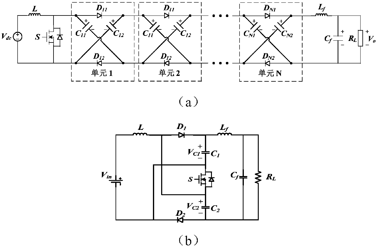
A technology of switched capacitor network and DC converter, which is applied in the direction of high-efficiency power electronic conversion, no intermediate conversion to AC conversion equipment, electrical components, etc., which can solve the problem of diode current, large voltage stress, circuit inability to work, and reduced voltage boosting capacity. System efficiency and other issues to achieve the effect of increasing voltage gain, reducing control complexity, and broad application prospects

Active Publication Date: 2018-02-23
XI AN JIAOTONG UNIV
View PDF5 Cites 7 Cited by
  • Summary
  • Abstract
  • Description
  • Claims
  • Application Information

AI Technical Summary

Problems solved by technology

However, affected by the parasitic parameters of the device in the actual circuit, the circuit cannot work at the limit duty cycle and the boosting capability is limited
The current and voltage stress of the diode are large, and at the same time, there is a reverse recovery problem due to hard turn-off, which leads to serious switching loss and EMI problems, reducing the efficiency of the system
figure 1 (a) When S=ON in the main circuit shown in (a), two capacitors with voltage source characteristics appear to directly pass through the short-circuit charging and discharging process of the power semiconductor device, resulting in a huge inrush current, which increases the loss of the device and reduces the efficiency of the circuit.

Method used


Image

  • Multi-unit coupled inductor switch capacitor network high-gain direct-current converter
  • Multi-unit coupled inductor switch capacitor network high-gain direct-current converter
  • Multi-unit coupled inductor switch capacitor network high-gain direct-current converter

Examples


Embodiment Construction

[0025] The present invention will be further described below in conjunction with the accompanying drawings.

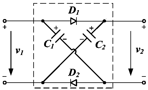
[0026] see figure 2 , the present invention includes the input power supply V in , controllable switch tube S, coupled inductors with multiple windings on the secondary side, multiple two-port diode capacitor boost units, output rectifier diodes, output capacitors, and output load R L ;Such as image 3 As shown, the two-port diode capacitor boost unit includes a first diode D 1 , the second diode D 2 , the first DC capacitor C 1 and a second DC capacitor C 2 ; The first DC capacitor C 1 The anode of the first diode D 1 anode of the second DC capacitor C 2 The anode of the first diode D 1 The cathode; the first DC capacitor C 1 The cathode of the second diode D 2 anode of the second DC capacitor C 2 The cathode of the second diode D is connected 2 the cathode; the first diode D 1 cathode and the second diode D 2 The anode of is the output terminal of the...


PUM


Abstract

The invention discloses a multi-unit coupled inductor switch capacitor network high-gain direct-current converter. The converter comprises an input end power supply V<in>, a controllable switching tube S, a secondary side multi-winding coupled inductor, multiple two-port diode capacitor voltage-boosting units, a diode D, an output capacitor C and an output end load RL; the main circuit topology, by fully combining the characteristic of the multi-winding coupled inductor and the diode capacitor voltage-boosting units, overcomes the inherent defects of the impact current of a diode capacitor network, so that the voltage gain is obviously improved, the voltage stress of the switching tube is lowered, natural switch-off of all diodes is realized, the switching loss is lowered, and electric energy conversion efficiency is improved; and the multi-unit coupled inductor switch capacitor network high-gain direct-current converter has wide application prospect in a new energy distributed type power generation system.

Description

technical field [0001] The invention belongs to the field of grid-connected micro-grids such as new energy photovoltaics and fuel cells, and relates to a high-gain non-isolated DC conversion technology, in particular to a multi-unit coupled inductor switched capacitor network high-gain DC converter. Background technique [0002] Solar energy and fuel cells are the two fastest-growing forms of new energy in recent years, and they will become one of the most promising energy sources in the future. However, photovoltaic panels can usually be connected in series to increase the output voltage level, but affected by cloud cover and bad weather, the output voltage is low and fluctuates in a wide range. Fuel cells also have the above-mentioned problems. Therefore, the converter of grid-connected interface must have wide input and high boost capability. The traditional voltage source inverter is based on the step-down principle and the DC side voltage must be greater than the peak...

Claims


Application Information

Patent Timeline
Patent Type & Authority Applications(China)
IPC IPC(8): H02M3/07
CPCH02M3/07H02M1/0054Y02B70/10
Inventor 张岩李新颖丁恺诚刘进军
Owner XI AN JIAOTONG UNIV
Learn More