Eureka AIR delivers breakthrough ideas for toughest innovation challenges, trusted by R&D personnel around the world.

Surface light source device using light emitting diodes

a light-emitting diode and surface light-emitting technology, which is applied in the direction of semiconductor devices, light-emitting devices, instruments, etc., can solve the problems of limited wavelength of light-emitting, low color rendering properties of phosphors such as yag:ce and a blue led, and the limitation of achieving the desired natural white light. , to achieve the effect of improving the overall brightness

Active Publication Date: 2008-04-03
SAMSUNG ELECTRONICS CO LTD
View PDF8 Cites 104 Cited by
  • Summary
  • Abstract
  • Description
  • Claims
  • Application Information

AI Technical Summary

Benefits of technology

[0011] An aspect of the present invention provides a surface light source device using light emitting diodes, the device capable of providing relatively higher color rendering index by employing a plurality of phosphors providing different wavelengths from one another, respectively, and greatly improving color conversion efficiency by appropriately changing a structure of color conversion layers.
[0018] The housing may include an inner surface formed of a reflective surface to greatly improve overall brightness.

Problems solved by technology

However, LEDs emit light with a limited wavelength.
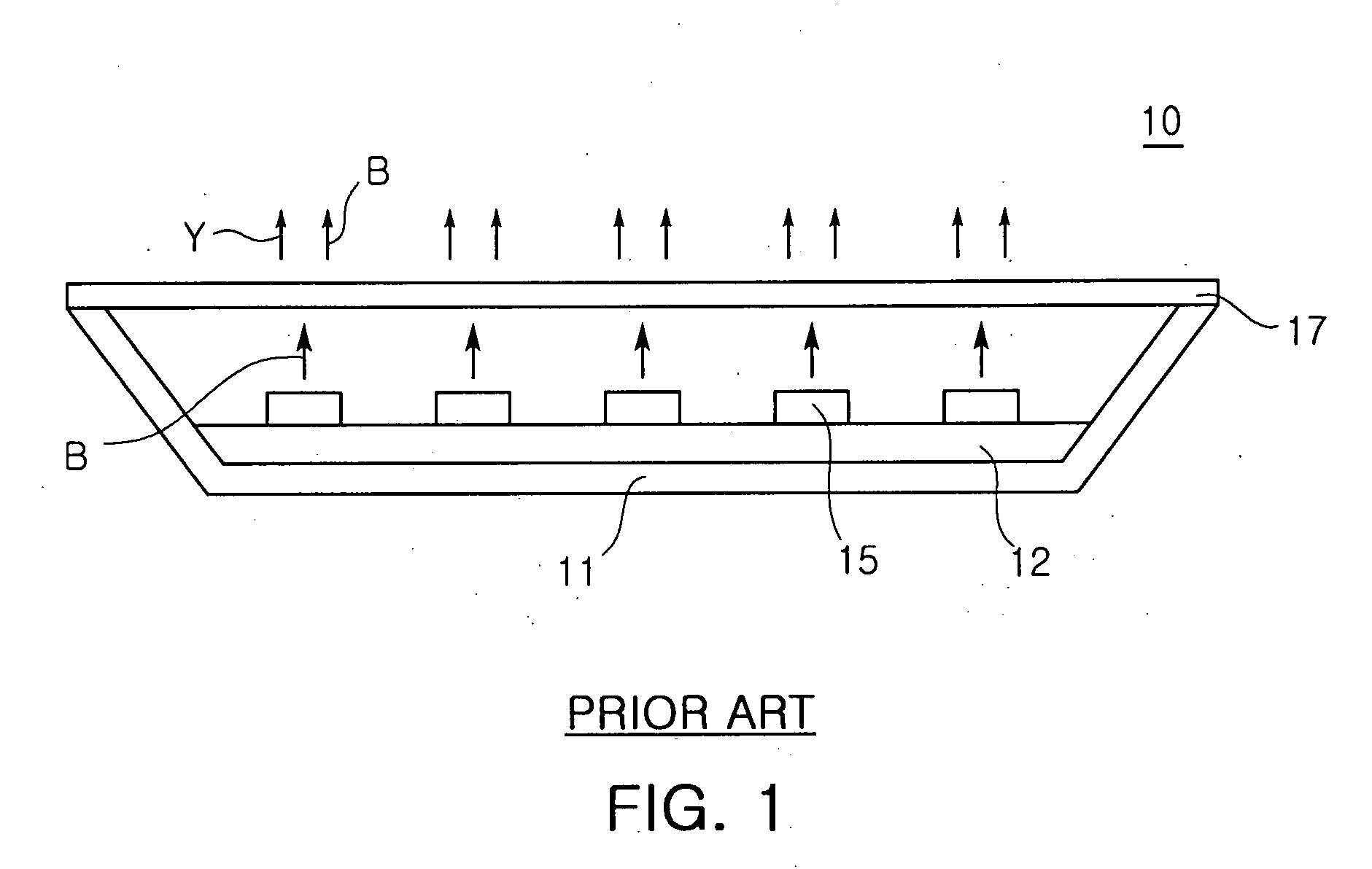
However, generally, a combination of a yellow emitting phosphor such as YAG:Ce and a blue LED shows low color rendering properties.
That is, since a wavelength of the white light obtained by using the yellow emitting phosphor is distributed only in blue and yellow, there is a limitation on embodying desired natural white light due to low color rendering properties.

Method used


Image

  • Surface light source device using light emitting diodes
  • Surface light source device using light emitting diodes
  • Surface light source device using light emitting diodes

Examples


Embodiment Construction

[0023] Exemplary embodiments of the present invention will now be described in detail with reference to the accompanying drawings.

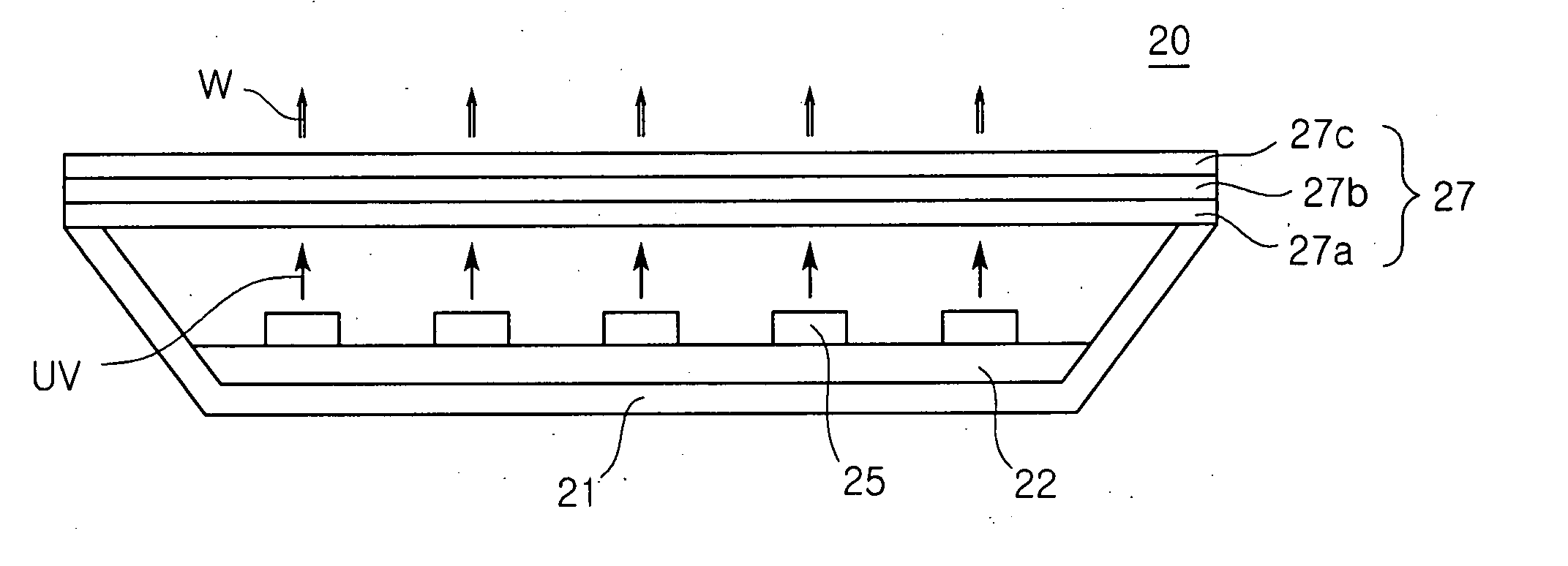
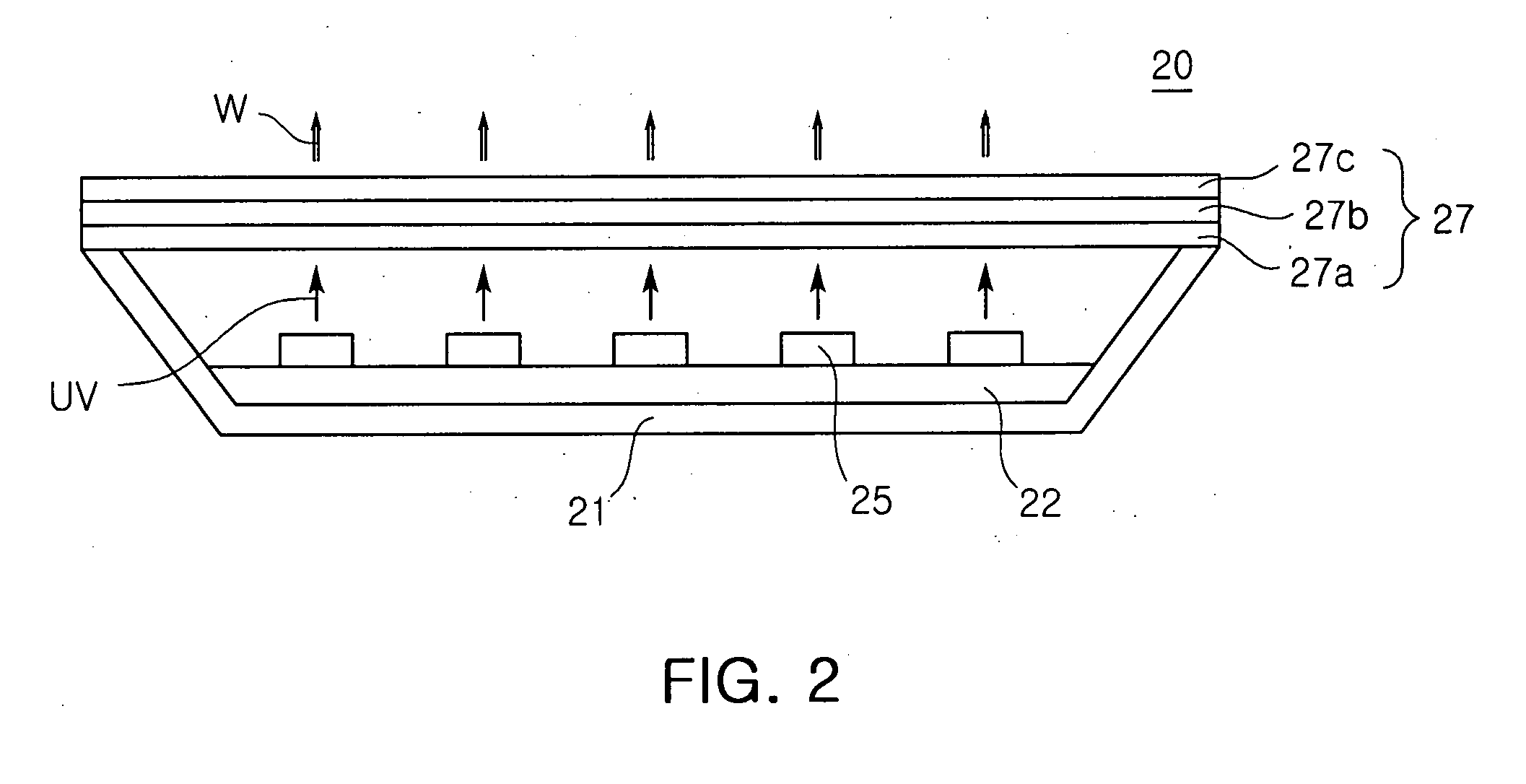
[0024]FIG. 2 is a side cross-sectional view illustrating a surface light source device 20 for lighting, according to an exemplary embodiment of the present invention.

[0025] Referring to FIG. 2, the surface light source device 20 emitting white light includes a housing 21 having a top opening and a light emitting diode (LED) board 22 disposed in the housing 21. In this case, though not shown, to improve overall brightness, an inner surface of the housing 21 may be coated with a material such as a reflective metal to be provided as a reflective surface.

[0026] A circuit is provided to drive a plurality of LEDS 25. The circuit may be embodied to drive in parallel or in serial. The LED board 22 may be embodied as a printed circuit board (PCB). The LED 25 may be one of ultra violet and near ultra violet LED emitting light having a wavelength of 200 to 500 nm...


PUM


Abstract

A surface light source device using light emitting diodes, the device including: a housing having a top opening to emit light; a light emitting diode board disposed on an inner bottom surface of the housing, the board on which a plurality of light emitting diodes are arranged; and a color conversion laminate formed by depositing a plurality of phosphor-mixed resin layers containing phosphors, the layers disposed at a top of the opening of the housing and providing light having different wavelengths.

Description

CROSS-REFERENCE TO RELATED APPLICATIONS [0001] This application claims the priority of Korean Patent Application No. 2006-0097237 filed on Oct. 02, 2006, in the Korean Intellectual Property Office, the disclosure of which is incorporated herein by reference. BACKGROUND OF THE INVENTION [0002] 1. Field of the Invention [0003] The present invention relates to a surface light source device using light emitting diodes (LEDs), and more particularly, to a surface light source device using LEDs having a color conversion structure capable of providing high efficiency. [0004] 2. Description of the Related Art [0005] In general, due to low-power driving and excellent light efficiency, semiconductor light emitting diodes (LEDs) are generally applied as liquid crystal display (LCD) backlight, vehicle light, and home lighting. However, LEDs emit light with a limited wavelength. Therefore, it is required a method of obtaining white light needed in surface light source. [0006] There has been a met...

Claims


Application Information

Patent Timeline
IPC IPC(8): F21V9/16
CPCC09K11/7734C09K11/7737C09K11/7794G02B5/20F21V9/16F21Y2101/02F21V3/04F21Y2115/10F21V13/08F21V9/38
Inventor KIM, YONG TAELEE, MIN SANGLEE, DONG YEOUL
Owner SAMSUNG ELECTRONICS CO LTD
Why Eureka
Eureka Blog
Learn More