
Dual-current observer-based permanent-magnet synchronous motor control method

A permanent magnet synchronous motor, current observer technology, applied in motor generator control, electronic commutation motor control, control system and other directions, can solve problems such as increased cost, no sensor interference, unsolved theoretical problems, etc.

Inactive Publication Date: 2018-02-16
NINGBO UNIVERSITY OF TECHNOLOGY
View PDF4 Cites 1 Cited by
  • Summary
  • Abstract
  • Description
  • Claims
  • Application Information

AI Technical Summary

Problems solved by technology

However, reducing cost and improving performance have always been the goals pursued in the field of motor control, and the use of encoders undoubtedly brings problems such as installation, maintenance, interference, and increased costs, so sensorless technology has become an important research direction
At present, sensorless technology mainly has the problem of external interference, which is still in the stage of theoretical exploration, and there are still some theoretical problems that have not been resolved.

Method used


Image

  • Dual-current observer-based permanent-magnet synchronous motor control method
  • Dual-current observer-based permanent-magnet synchronous motor control method
  • Dual-current observer-based permanent-magnet synchronous motor control method

Examples


Embodiment Construction

[0056] The implementation manners of the present invention are described below through specific examples, and those skilled in the art can easily implement the content disclosed in this specification.

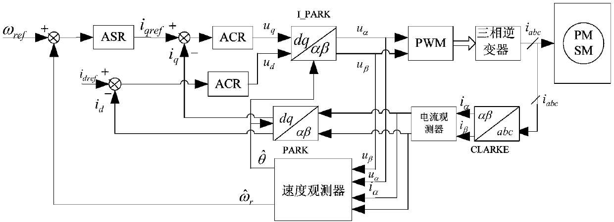
[0057] Step 1: For the permanent magnet synchronous motor with convex substructure, establish a mathematical model, and its model in the static coordinate system α, β is

[0058]

[0059]

[0060] v α =-ψ f ω r sin(θ) (3)

[0061] v β =-ψ f ω r cos(θ) (4)

[0062] where i α ,i β Respectively, the stator α, β axis current, u α ,u β Respectively, the stator α, β axis voltage, v α ,v β is the counter electromotive force, R is the stator resistance, L is the stator inductance, T α , T β Respectively, the electromagnetic torque of the stator α, β axis, ψ f is the flux linkage, ω r , θ are speed and position respectively;

[0063] Step 2: Considering parameter changes, design a current observer as

[0064]

[0065]

[0066] The first estimate of the back...


PUM


Abstract

The invention provides a dual-current observer-based permanent-magnet synchronous motor control method. By the dual-current observer-based permanent-magnet synchronous motor control method, a motor encoder-free control technology is achieved. The dual-current observer-based permanent-magnet synchronous motor control method comprises the steps of firstly, building a permanent-magnet synchronous motor mathematical model; secondly, designing two current observers, and further obtaining a counter electromotive value from the two current observers; thirdly, verifying system stability by employing aLyapunov function; and finally, determining a system a parameter according to a simulation result. A sliding-mode variable structure method is employed during the design process of the current observers, the current estimation accuracy is effectively improved, the influence of external interference is greatly reduced by the dual current observers, and accurate estimation of a speed and a positionof the motor is achieved; and due to the application of a mechanical encoder in the permanent-magnet synchronous motor, the cost is increased, the reliability is reduced, thus, the various defects ofthe prior art are effectively overcome, and the dual-current observer-based permanent-magnet synchronous motor control method has high application value.

Description

technical field [0001] The invention relates to a control method of a permanent magnet synchronous motor based on a dual current observer. Background technique [0002] Permanent magnet synchronous motor (PMSM) has very good low-speed performance, can realize high-speed control of weak field, wide speed range, high dynamic characteristics and high efficiency, and does not need excitation current, which improves motor efficiency and power density. Permanent magnet synchronous Motors have become the mainstream choice for servo systems and are widely used in CNC machine tools, industrial robots and other fields. [0003] With the development of microelectronic technology, microprocessor, and control technology, many control strategies with complex algorithms can be applied to motor control. At present, the control strategies for the mathematical model of AC motors mainly include slip frequency control, vector control, decoupling control, direct torque control, etc. Among them,...

Claims


Application Information

Patent Timeline
IPC IPC(8): H02P21/22
CPCH02P21/22
Inventor 何金保骆再飞易新华
Owner NINGBO UNIVERSITY OF TECHNOLOGY
Learn More