Flow-adaptive drainage ditch

A self-adaptive, drainage ditch technology, applied in the direction of roof, building, building structure, etc., can solve the problems of a large amount of water accumulation and insufficient drainage speed, and achieve the effects of rapid drainage, small space occupation, and low cost.

Active Publication Date: 2018-02-16
CHONGQING UNIV OF POSTS & TELECOMM
View PDF12 Cites 0 Cited by
  • Summary
  • Abstract
  • Description
  • Claims
  • Application Information

AI Technical Summary

Problems solved by technology

[0003] In view of this, the present invention is to provide a flow self-adaptive drainage ditch to solve the problem of a large amount of water accumulation caused by insufficient drainage speed

Method used


Image

  • Flow-adaptive drainage ditch
  • Flow-adaptive drainage ditch
  • Flow-adaptive drainage ditch

Examples


Embodiment Construction

[0021] Embodiments of the present invention are described below through specific examples, and those skilled in the art can easily understand other advantages and effects of the present invention from the content disclosed in this specification. The present invention can also be implemented or applied through other different specific implementation modes, and various modifications or changes can be made to the details in this specification based on different viewpoints and applications without departing from the spirit of the present invention. It should be noted that the diagrams provided in the following embodiments are only schematically illustrating the basic concept of the present invention, and the following embodiments and the features in the embodiments can be combined with each other in the case of no conflict.

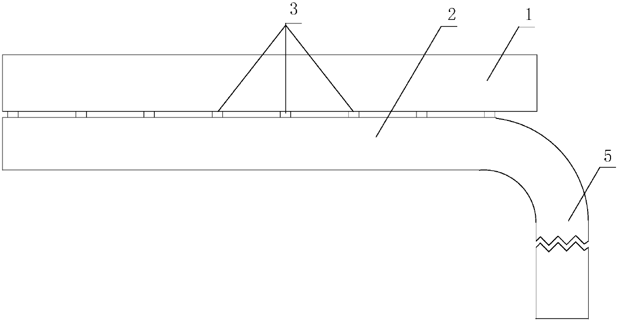
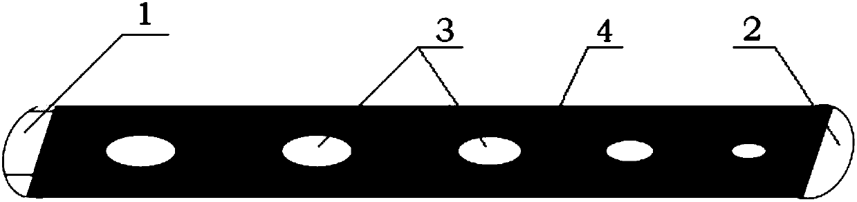
[0022] see Figure 1-3 , The component labels in the accompanying drawings represent respectively: sump 1, drainage tank 2, water guide hole 3, dividing plat...


PUM


Abstract

The invention discloses a flow-adaptive drainage ditch and belongs to the field of drainage. The flow-adaptive drainage ditch is composed of a water collection tank on the upper layer, a drainage tankon the lower layer and a drain pipe connected with the water outlet end of the drainage tank; the water collection tank and the drainage tank communicate through a series of multiple water guiding holes with the different cross section areas; and the multiple water guiding holes are formed in the bottom of the water collection tank and distributed at intervals in the tank length direction of thewater collection tank, and the cross section areas of the multiple water guiding holes are sequentially decreased step by step in the flow guiding direction of the drainage tank. According to the flow-adaptive drainage ditch, even if the ditch is in the horizontal direction, rainwater in the water collection tank can be taken away rapidly in the large rainfall period while drainage of the small-rainfall or large-gradient ditch is not affected, the situation that water is accumulated because the water collection tank is flat is avoided, and the flow-adaptive drainage ditch has the advantages ofbeing rapid in flood drainage, simple in structure, easy to manufacture, low in cost, convenient to construct, adaptive in displacement and adjustable in mounting; and in addition, a rainwater pipe culvert and a sewage pipe culvert can be vertically laid in the same position, and thus the advantages of occupying the small space and saving investment are achieved.

Description

technical field [0001] The invention belongs to the technical field of drainage and relates to a flow self-adaptive drainage ditch. Background technique [0002] In the existing drainage system, such as roof drainage (gutter, eaves and gutters), such a structure has a dilemma that is difficult to solve, that is, the greater the inclination angle of the water tank, the better the drainage effect, but the less beautiful; if the inclination angle If it is small, it is easy to cause rainwater to overflow directly from the gutter due to the slow drainage speed during heavy rain. Another example is open ditch drainage and hidden ditch drainage in surface drainage. Such a structure is prone to large amounts of water accumulation due to slow drainage speed during heavy rainstorms in flat terrain. Simply put, as in figure 1 As shown, when the drainage groove is approximately horizontal, the drop between the two ends of the drainage groove can only be the maximum depth of the draina...

Claims


Application Information

Patent Timeline
Patent Type & Authority Applications(China)
IPC IPC(8): E04D13/064
CPCE04D13/064
Inventor 朱红军钱鹰
Owner CHONGQING UNIV OF POSTS & TELECOMM
Why Eureka
Try Eureka