LDO (low dropout regulator) circuit and LDO implementing method
A circuit and compensation circuit technology, applied in the direction of adjusting electrical variables, control/regulation systems, instruments, etc., can solve problems such as failure to follow, LDO circuit stability decline, etc.
- Summary
- Abstract
- Description
- Claims
- Application Information
AI Technical Summary
Problems solved by technology
Method used
Image
Examples
Embodiment Construction
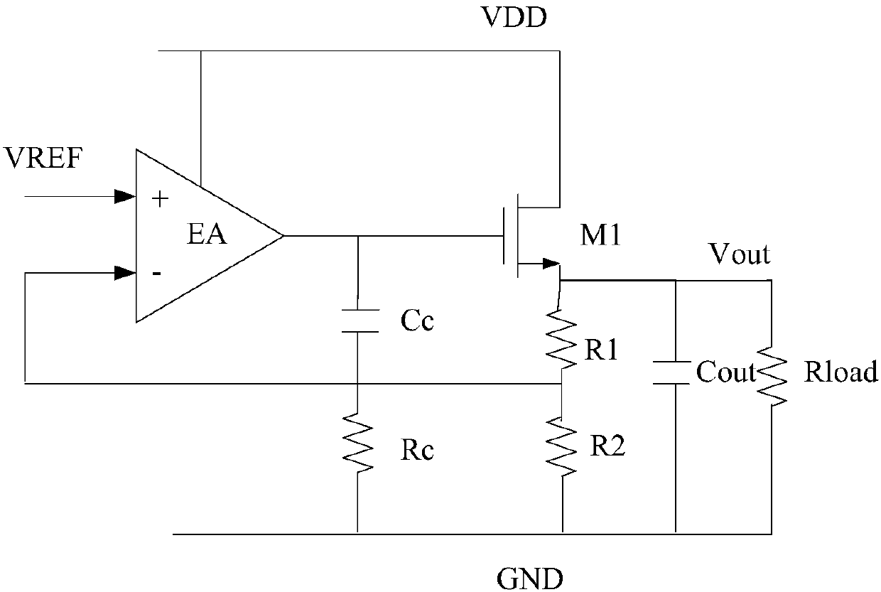
[0039] The circuit structure of the existing NMOS LDO circuit in integrated circuit design is briefly introduced above, and the working principle of the NMOS LDO circuit will be described in detail below.
[0040] figure 1 In the circuit shown, according to the pole frequency formula at the output node It can be seen that when the output current is small, the load Rload is large, and the transconductance gmp of the NMOS transistor M1 is small. At this time, the pole is located at a low frequency; when the output current is large, the load Rload is small, and the transconductance gmp of the NMOS transistor M1 is small. The transconductance gmp is larger, at this time, the pole is located at a higher frequency. Regardless of whether the pole is located at a lower frequency or a higher frequency, it will affect the stability of the NMOS LDO circuit, especially when the frequency of the pole is less than the unity gain bandwidth of the loop in the NMOS LDO circuit. Compensation ...
PUM
 Abstract
Description
Claims
Application Information
 - Generate Ideas
- Intellectual Property
- Life Sciences
- Materials
- Tech Scout
- Unparalleled Data Quality
- Higher Quality Content
- 60% Fewer Hallucinations
Browse by: Latest US Patents, China's latest patents, Technical Efficacy Thesaurus, Application Domain, Technology Topic, Popular Technical Reports.
© 2025 PatSnap. All rights reserved.Legal|Privacy policy|Modern Slavery Act Transparency Statement|Sitemap|About US| Contact US: help@patsnap.com


