Method for controlling constant-voltage discharging of energy storage system of flywheel

A technology of constant voltage discharge and flywheel energy storage, applied in control/regulation systems, electrical components, regulating electrical variables, etc., can solve problems such as difficulty in adapting to constant voltage discharge requirements of flywheel energy storage devices, technical obstacles, circuit filtering difficulties, etc. Achieve the effect of improving circuit response capability, constant output voltage, and preventing line overcurrent

Inactive Publication Date: 2011-07-20
TIANJIN UNIV
View PDF1 Cites 6 Cited by
  • Summary
  • Abstract
  • Description
  • Claims
  • Application Information

AI Technical Summary

Problems solved by technology

Considering the nonlinearity of power electronic components and the change of the voltage drop rate, the traditional linear control method is difficult to meet the constant voltage discharge requirements of the flywheel energy storage device, and the sliding mode control needs to constantly change the switching tube in the DC / DC circuit. The switching frequency makes the filtering of the circuit more difficult, and its highest switching frequency needs to be close to infinity, which makes the practical application technical obstacles; the realization of the nonlinear neural network control method requires a lot of experiments, and the neuron weight is constantly optimized to realize the neural network. Tuning of meta parameters

Method used


Image

  • Method for controlling constant-voltage discharging of energy storage system of flywheel
  • Method for controlling constant-voltage discharging of energy storage system of flywheel
  • Method for controlling constant-voltage discharging of energy storage system of flywheel

Examples


Embodiment Construction

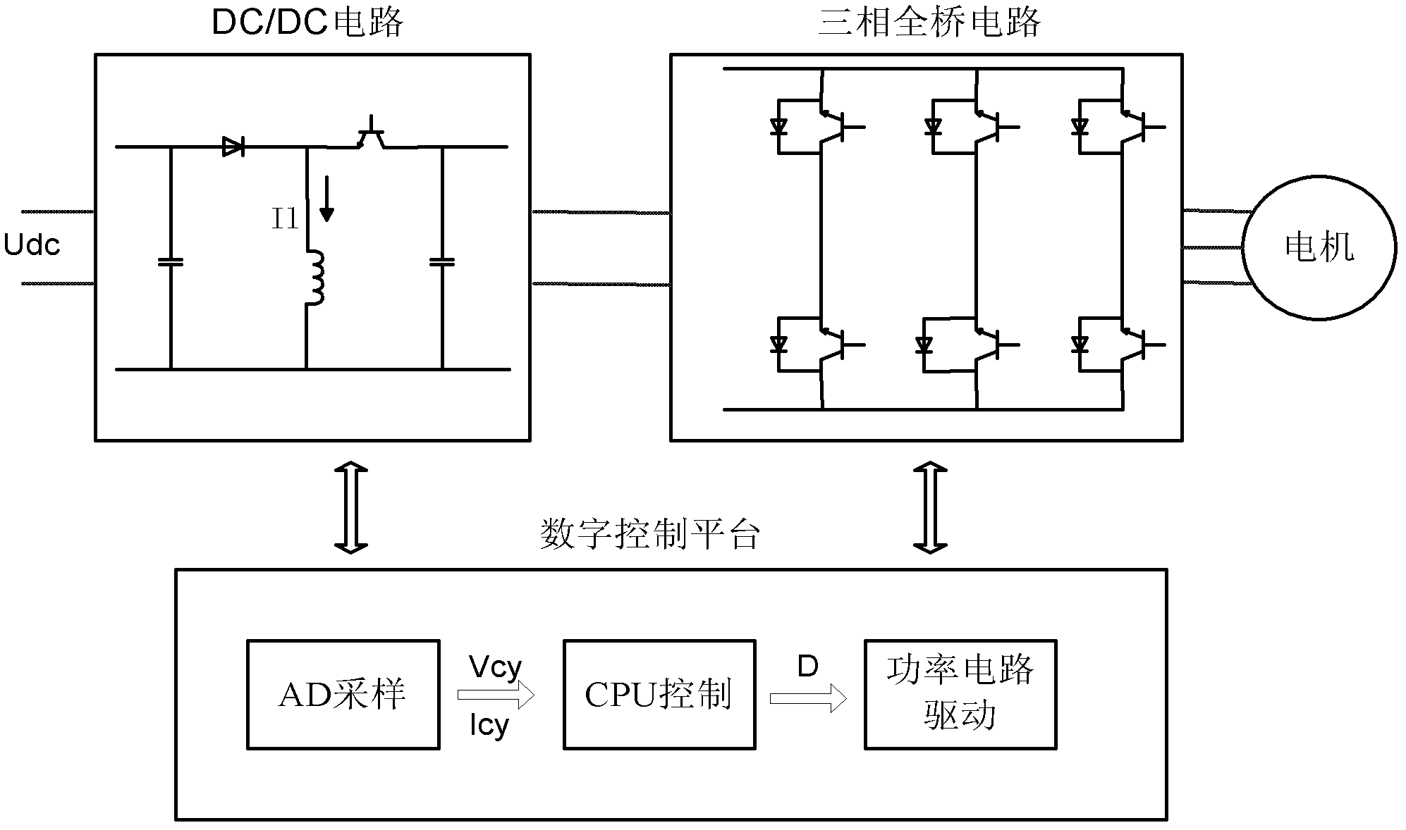
[0022] The invention is aimed at the discharge control of a flywheel device containing a three-phase brushless DC motor, and requires the DC / DC circuit to transmit energy by inductance. The rapid discharge control of the DC / DC circuit of the flywheel energy storage control motor involved in the present invention is based on a digital control platform, and its control method is mainly completed through the following two links: a voltage adjustment unit and a current adjustment unit.

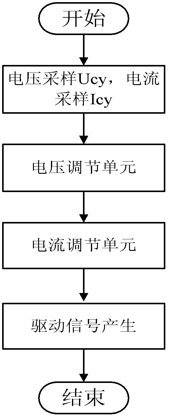
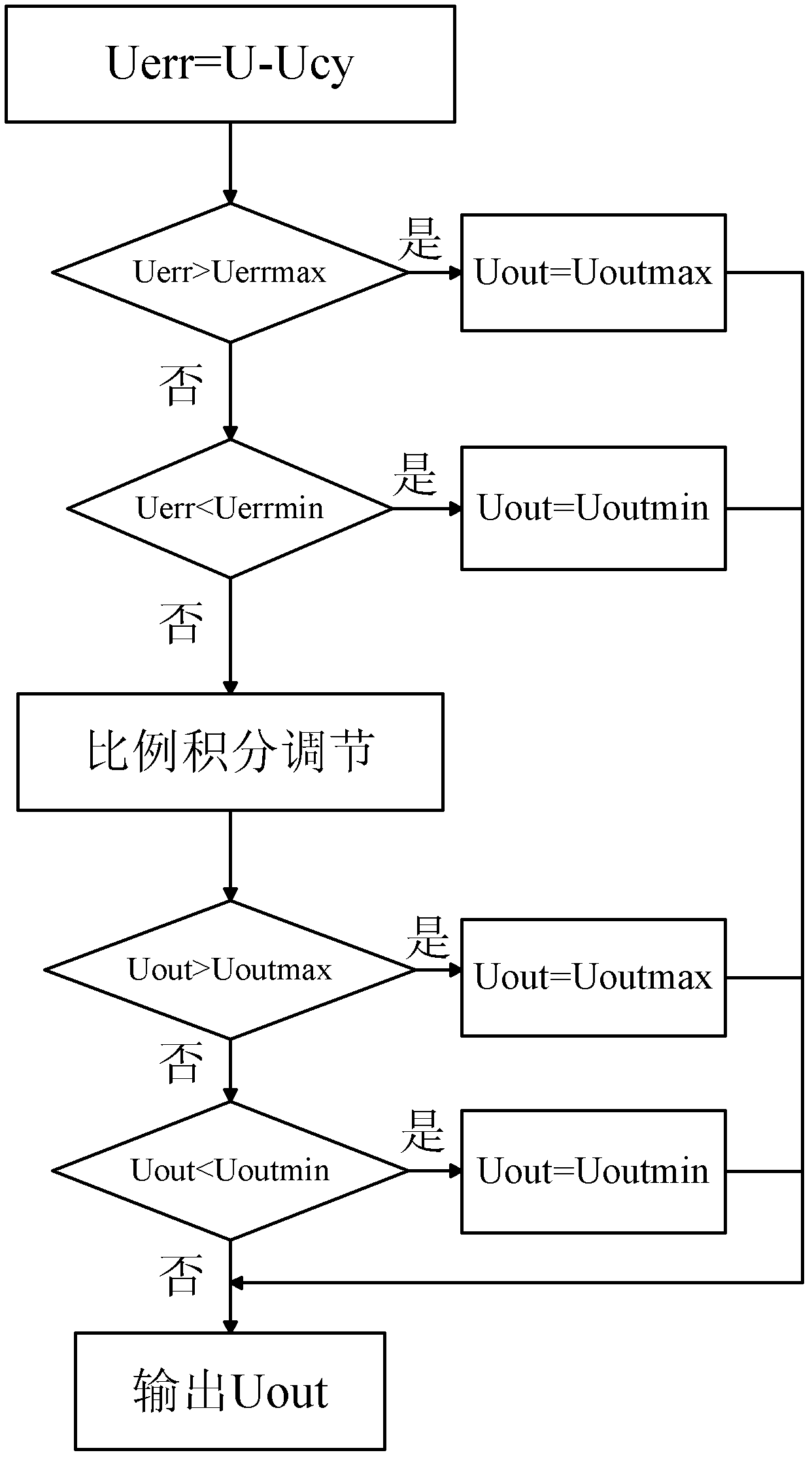
[0023] The primary hardware circuit includes DC / DC circuit, three-phase full-bridge circuit and motor and its driving circuit, such as figure 1 As shown, the three-phase full-bridge circuit performs uncontrolled rectification. The digital control platform has a digital processor and a high-speed A / D chip. Such as figure 2 As shown, the control algorithm includes A / D sampling, voltage and current regulation unit, and drive signal generation.

[0024] 1A / D sampling

[0025] Real-time sampling o...


PUM


Abstract

The invention belongs to the technical field of generation, conversion or distribution of power, and relates to a method for controlling constant-voltage discharging of an energy storage system of a flywheel. The method comprises the following steps of: arranging a voltage regulation unit, comparing a direct-current output voltage of a direct-current/direct-current (DC/DC) circuit with a set voltage, when a difference between the output voltage and the set voltage is large, regulating according to maximum and minimum outputs, and when the difference is small, performing proportional integration regulation output; arranging a current regulation unit, comparing a sampled current average value with a current set value, when a difference between the sampled current average value with the current set value is large, regulating according to maximum and minimum outputs, when the difference between the sampled current average value with the current set value is small, performing the proportional integration regulation, and limiting the amplitude of the outputs simultaneously; and regulating a duty ratio D of a driving signal by using a comparator and a counter of a digital control chip according to the output of the current regulation unit so as to drive the high-power DC/DC circuit. By the method, the output direct-current voltage can be kept constant under the condition of a certaindischarging depth during quick discharging.

Description

technical field [0001] The invention belongs to the technical field of electric power generation, transformation or distribution, and relates to a control method for a flywheel energy storage system. Background technique [0002] With the increasing pressure on global resources and environment, the development of green energy and the realization of sustainable development have become the focus of attention of all countries. As a clean, environmentally friendly, and high-power energy storage method, the flywheel energy storage power supply has the advantages of long service life, high stability, and fast charging and discharging speed. Get more and more promotion and application. [0003] Brushless DC motors have the advantages of high reliability, long working life, high efficiency, and good control performance, and are widely used in flywheel energy storage devices to realize the mutual conversion of electrical energy and mechanical energy. At present, a flywheel energy s...

Claims


Application Information

Patent Timeline
Patent Type & Authority Applications(China)
IPC IPC(8): H02M7/12H02M3/156
Inventor 李永丽袁金桥谈震孙杰李博通
Owner TIANJIN UNIV
Why Eureka
Try Eureka