Multilayer filter

A filter and stacking direction technology, applied in the direction of inductors, fixed inductors, electrical components, etc., can solve the problem of insertion loss deterioration, achieve the effect of suppressing eddy current loss and improving insertion loss

Active Publication Date: 2018-02-06
MURATA MFG CO LTD
View PDF14 Cites 4 Cited by
  • Summary
  • Abstract
  • Description
  • Claims
  • Application Information

AI Technical Summary

Problems solved by technology

The greater the eddy current loss, the worse the insertion loss will be

Method used


Image

  • Multilayer filter
  • Multilayer filter
  • Multilayer filter

Examples


Embodiment Construction

[0018] Hereinafter, embodiments of the present invention will be described in detail with reference to the drawings. In addition, the same symbols are assigned to the same or corresponding parts in the drawings, and the description thereof will not be repeated in principle.

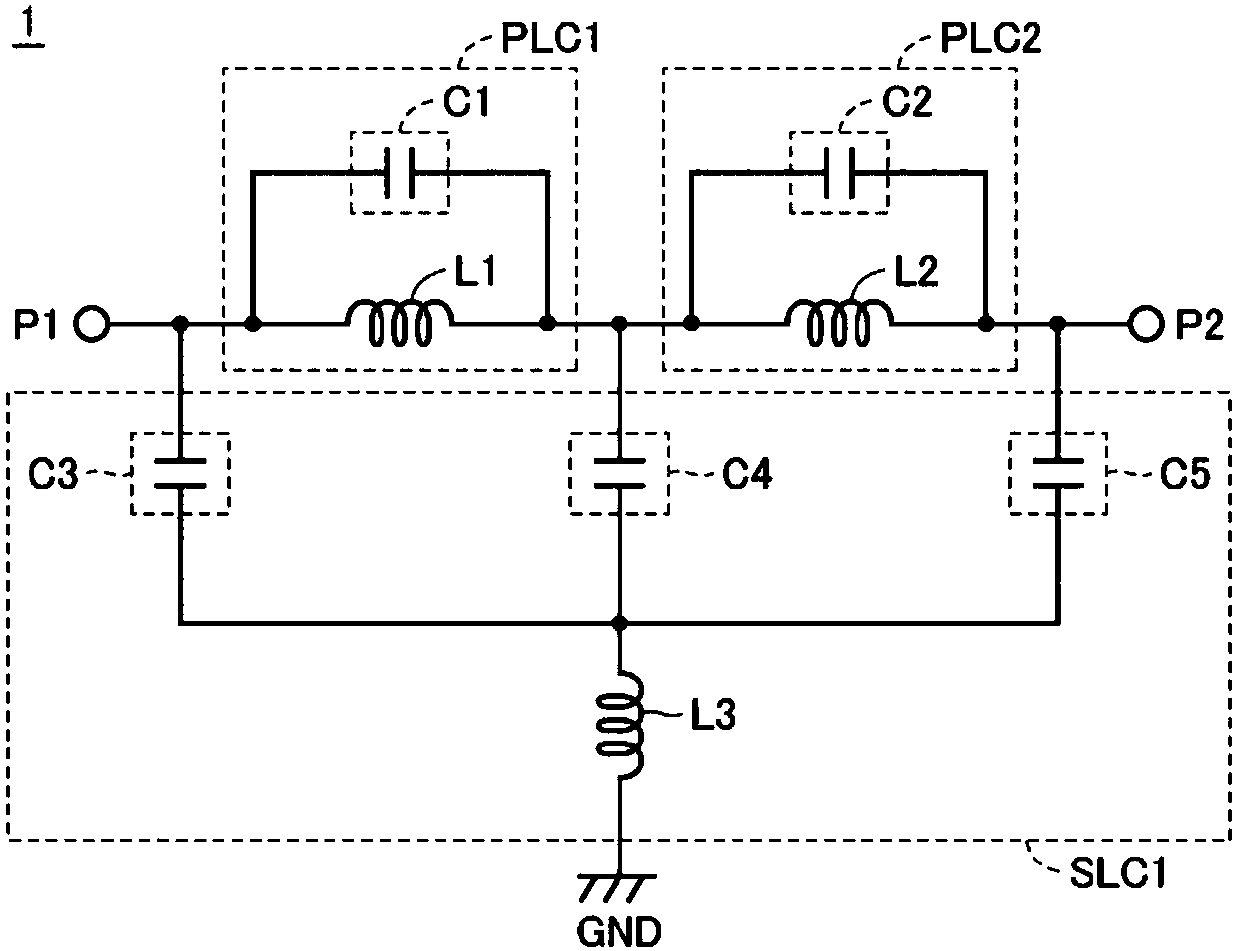
[0019] figure 1 It is an equivalent circuit diagram of a low-pass filter 1 as an example of the multilayer filter according to the embodiment. Such as figure 1 As shown, the low-pass filter 1 includes: input / output terminals P1, P2; LC parallel resonators PLC1, PLC2; and LC series resonator SLC1.

[0020] The LC parallel resonator PLC1 includes an inductor L1 and a capacitor C1. One end of the inductor L1 is connected to the input / output terminal P1. Capacitor C1 is connected in parallel with inductor L1.

[0021] LC parallel resonator PLC2 includes an inductor L2 and a capacitor C2. The inductor L2 is connected between the other end of the inductor L1 and the input / output terminal P2. Capacitor C2...


PUM


Abstract

A multilayer filter includes dielectric layers, a first terminal, a second terminal, a first inductor, a second inductor, and first to fifth capacitors. In a stacking direction of the dielectric layers, at least one of a first air-core portion defined by the first inductor and a second air-core portion defined by the second inductor includes, in a region from the first inductor layer to the secondinductor layer, a region enabling magnetic flux to pass therethrough without being obstructed by the first to fifth capacitors and the third inductor.

Description

technical field [0001] The present invention relates to a multilayer filter including LC resonators. Background technique [0002] Currently, a multilayer filter including an LC resonator is known. For example, Japanese Unexamined Patent Publication No. 2009-182376 (Patent Document 1) discloses a multilayer low-pass filter including an LC parallel resonator and an LC series resonator. With this multilayer low-pass filter, it is possible to increase the The amount of attenuation of a specific narrow frequency band that exists in the stop band of a low-pass filter. [0003] Patent Document 1: Japanese Patent Laid-Open No. 2009-182376. [0004] For the multilayer filter, there is a trend of miniaturization due to strong demand from portable wireless communication devices in recent years. Along with miniaturization, the arrangement space of inductors and capacitors in the multilayer filter is strongly restricted. As in the multilayer low-pass filter disclosed in Japanese Pate...

Claims


Application Information

Patent Timeline
Patent Type & Authority Applications(China)
IPC IPC(8): H03H7/01H03H1/00
CPCH03H7/0115H03H7/1725H03H7/1758H03H7/1766H03H2001/0085H01F17/0013H01F2017/0026H03H7/03
Inventor 增田博志汤浅留美子
Owner MURATA MFG CO LTD
Why Eureka
Try Eureka