
Phase shift device

a phase shift and phase shift technology, applied in the direction of waveguide type devices, capacitors with voltage varied dielectrics, slot antennas, etc., can solve the problems of increasing the demand for reconfigurable components, shortening the available frequency spectrum of radio communications, and lcp material is not tunable with respect to the relative permittivity of this material, so as to achieve fast and cheap fabrication, easy and cost-saving fabrication of such a device, and less losses

Active Publication Date: 2018-11-27
ALCAN SYST GMBH
View PDF10 Cites 10 Cited by
  • Summary
  • Abstract
  • Description
  • Claims
  • Application Information

AI Technical Summary

Benefits of technology

The patent text describes a new design for a planar transmission line that includes tunable components that can be controlled to adjust the phase of signals transmitted through the line. These components, known as varactors, are made up of a special material that can be controlled by a bias voltage. The design of the transmission line is optimized to minimize loss, reduce interference, and control the phase of signals. The use of serially connected dielectric tunable components connected by a non-overlapping section of the signal electrode further enhances the performance of the transmission line.

Problems solved by technology

The shortage in the available frequency spectrum for radio communications and the requirement for more functionality in smaller volume increase the demand for reconfigurable components.
However, the LCP material is not tunable with respect to the relative permittivity of this material.
Therefore, due to the lack of tunable characteristic features that are relevant for the configuration of a tunable RF device, making use of LCPs is not convenient for designing of a tunable device such as a varactor.
One of the known drawbacks of such devices is the high metallic loss of the CPW.
This results in reduced tuning efficiency and high insertion loss of such an artificial transmission line.

Method used


Image

  • Phase shift device
  • Phase shift device
  • Phase shift device

Examples


Embodiment Construction

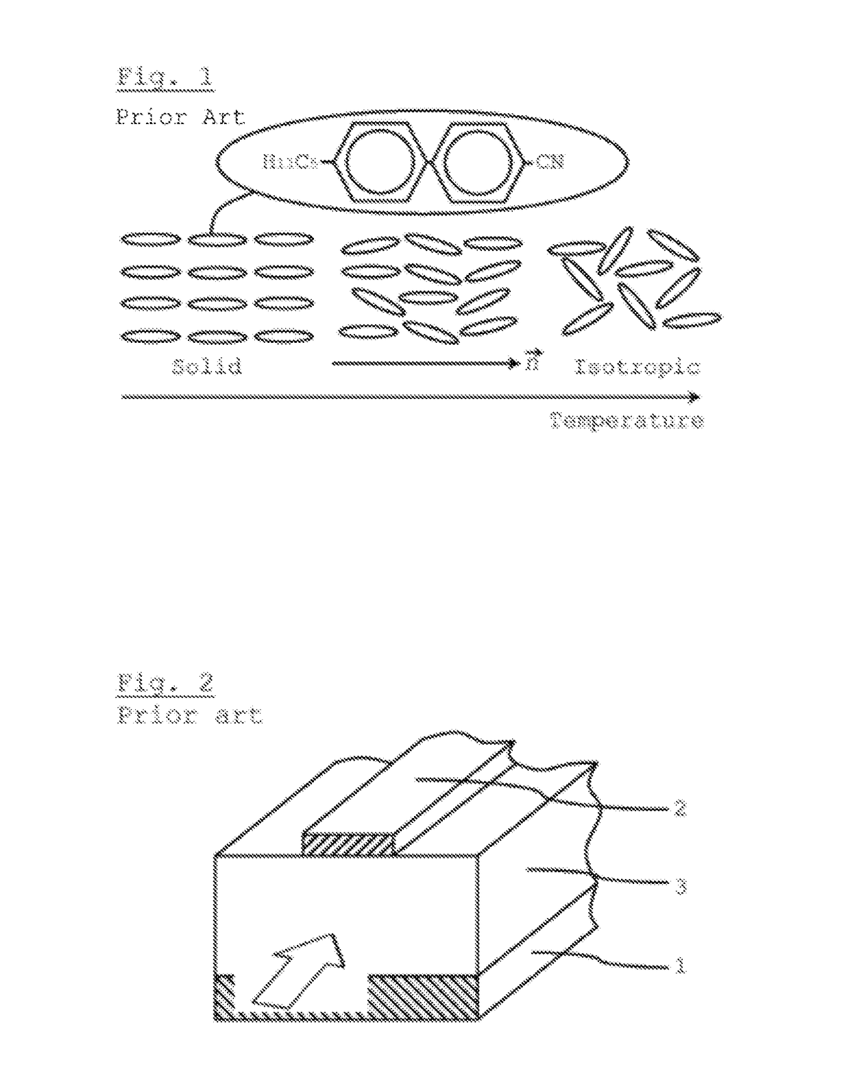
[0054]In general liquid crystal (LC) materials are anisotropic. This property stems from the rod-like shape of the molecules, as shown in an example structure of a typical LC molecule in FIG. 1. Here it is shown how the phase configuration of a LC material changes with increasing temperature. Together with the molecule in FIG. 1 the corresponding anisotropic dielectric properties are indicated. Since the material is liquid, the molecules feature only a weak molecular adhesion, and thus their orientation in the bulk can be changed. Owing to the rod-like shape, the molecules in a bulk tend to orient themselves in parallel order. The relative permittivity parallel to the molecule long axis is denoted as εr,∥ and perpendicular to the long axis as εr,.

[0055]If such a liquid crystal material is arranged between a signal electrode and a ground electrode of a strip shaped transmission line, the transmission speed of a radio frequency signal along the transmission line will be affected by th...


PUM


Abstract

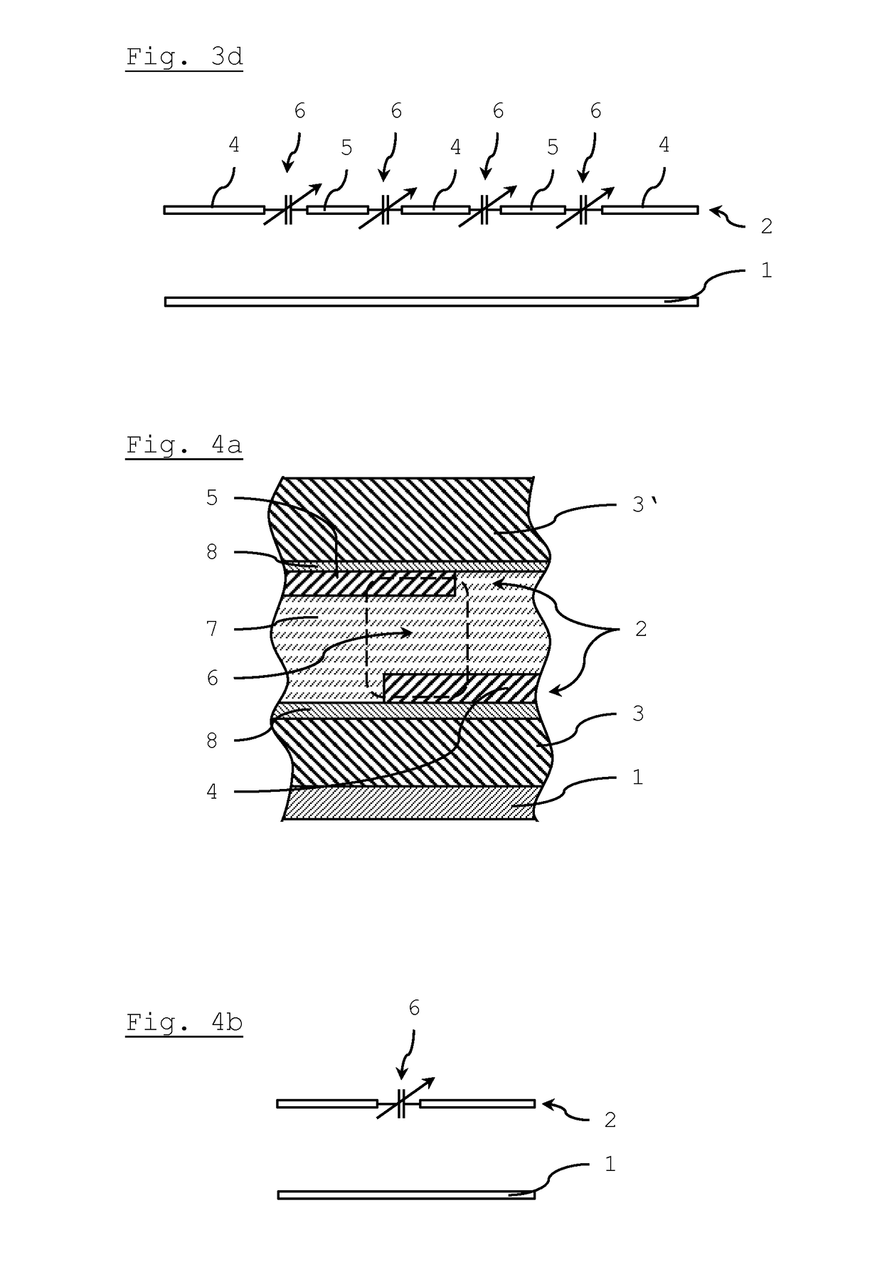
A phase shift device includes a planar transmission line that is formed by a signal electrode and a ground electrode which are separated by a dielectric substance, whereby the signal electrode of the planar transmission line is divided into several pieces and includes overlapping areas of adjacent pieces that are filled with a tunable liquid crystal material, thereby forming a dielectric tunable component (varactor) with a metal-insulator-metal type capacitor. The several pieces of the signal electrode are arranged at two or more different distance levels with respect to the ground electrode. The tunable liquid crystal material is arranged as a continuous layer between several pieces of the signal electrode that are arranged at two different distance levels.

Description

BACKGROUND AND SUMMARY[0001]The present invention relates a phase shift device with at least one tunable component. This phase shift is frequency independent (phase shifter) or frequency dependent (variable delay line).[0002]The shortage in the available frequency spectrum for radio communications and the requirement for more functionality in smaller volume increase the demand for reconfigurable components. Hereinafter radio frequency (RF) is meant a rate of oscillation in the range of about 3 kHz to 300 GHz, which corresponds to the frequency of radio waves and of the alternating currents which carry and transmit radio signals. Depending on the device requirements there are different possible solutions for phase shift devices like e.g. semiconductors, MEMS or tunable dielectrics to design agile RF components.[0003]Phase shift devices are one of the key elements for reconfigurable electronic beam steering antennas.[0004]From the state of the art the following documents are cited as ...

Claims


Application Information

Patent Timeline
Patent Type & Authority Patents(United States)
IPC IPC(8): H01P1/18H01Q9/04H01Q13/10
CPCH01P1/184H01P1/181H01Q13/106H01Q9/0457H01Q9/0407H01G7/06
Inventor JAKOBY, ROLFKARABEY, ONUR HAMZAHU, WENJUAN
Owner ALCAN SYST GMBH
Learn More