Combined type end mill for machining paper based honeycomb composite materials
A composite material and combined technology, used in milling cutters, metal processing equipment, manufacturing tools, etc., can solve the problems of chip bonding and high cutting temperature, and achieve the effect of reducing cutting deformation and cutting force.
- Summary
- Abstract
- Description
- Claims
- Application Information
AI Technical Summary
Problems solved by technology
Method used
Image
Examples
Embodiment 1
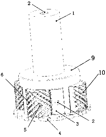
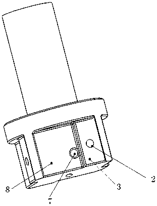
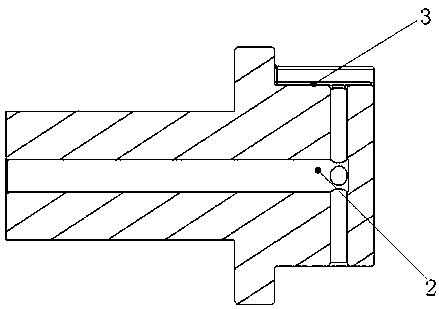
[0027] like figure 1 , figure 2 As shown, a combined end mill for processing paper-based honeycomb composite materials includes a cylindrical cutter body 9 and a tool shank 1 arranged on the upper end face of the cutter body 9 and connected with the cutter body 9 as a whole, and a cutter body 9 arranged on the cutter body 9 The disc serrated cutting knife 4 on the lower end surface, the knife handle 1 and the knife body 9 are coaxially installed. The cutter body 9 is provided with no less than four groups of positioning surfaces 8 , chip flutes 3 and internal cooling holes 2 that are equally spaced along the circumferential direction. like image 3 As shown, the inner cooling hole 2 is a through hole arranged inside the tool handle 1 and the tool body 9, one end of the inner cooling hole 2 penetrates the tool handle 1, an air inlet is formed on the upper end face of the tool handle 1, and the other end penetrates The cutter body 9 communicates with the chip flute 3 to for...
Embodiment 2
[0031] On the basis of the above-mentioned embodiment, this embodiment has been improved, and the improvement is as follows: Figure 4 , the surface of the cutting insert 6 is provided with a plurality of fine-toothed cutting edges 10 forming left and right double helical grooves. like Figure 4 As shown in the partial enlarged view of the medium fine tooth cutting edge 10, the rake angle on the A / A section of the fine tooth cutting edge 10 γ 1 The angle is 7~12°, the back angle α 1 The angle is 7~12°; the rake angle on the B / B section shown γ 2 The angle is 7~12°, the back angle α 2 The angle is 7~12°. Further, the upper rake angle of the serrated cutting edge 10 γ 1 = γ 2 =7~12°, back angle α 1 =α 2=7~12°. The cutting blade 6 is detachably fixed on the positioning surface 8 by the screw 5, and is connected with the cutter body 9. When the dust-like chips adhere to the cutting edge and are difficult to remove, a new blade can be used, and the replaced blade ...
PUM
 Abstract
Description
Claims
Application Information
 - R&D
- Intellectual Property
- Life Sciences
- Materials
- Tech Scout
- Unparalleled Data Quality
- Higher Quality Content
- 60% Fewer Hallucinations
Browse by: Latest US Patents, China's latest patents, Technical Efficacy Thesaurus, Application Domain, Technology Topic, Popular Technical Reports.
© 2025 PatSnap. All rights reserved.Legal|Privacy policy|Modern Slavery Act Transparency Statement|Sitemap|About US| Contact US: help@patsnap.com


