
Quantum dot radiofluorescence effect nuclear battery

A technology for quantum dots and nuclear batteries, applied in the field of quantum dot radiation-induced fluorescence effect nuclear batteries, can solve the problems of deviation from the optimal value, uncontrollable emission spectrum, and inability to achieve the conversion effect, so as to improve the conversion effect and increase the output. performance effect

Active Publication Date: 2018-01-19
NANJING UNIV OF AERONAUTICS & ASTRONAUTICS
View PDF2 Cites 4 Cited by
  • Summary
  • Abstract
  • Description
  • Claims
  • Application Information

AI Technical Summary

Problems solved by technology

[0005] However, traditional fluorescent materials such as phosphors and scintillators are used as intermediate energy conversion materials, and their emission spectra cannot be adjusted.
Therefore, for different types of semiconductor photovoltaic modules, the fluorescent layer made of traditional fluorescent materials cannot be perfectly adapted, which affects the output performance of the battery, deviates from the optimal value predicted by theoretical calculations, and cannot achieve the best energy conversion effect.
[0006] To sum up, there is currently a lack of a battery that can regulate the emission wavelength of fluorescent materials. By regulating the emission wavelength, it can be adapted to different semiconductor photovoltaic modules, making the battery output performance close to the optimal value predicted by theoretical calculations, and improving the overall output performance of nuclear batteries.

Method used


Image

  • Quantum dot radiofluorescence effect nuclear battery
  • Quantum dot radiofluorescence effect nuclear battery
  • Quantum dot radiofluorescence effect nuclear battery

Examples


Embodiment 1

[0036] The preparation method of quantum dot fluorescent layer comprises:

[0037] S1. Take methyl methacrylate and polymethyl methacrylate, and magnetically stir evenly at 55°C in a ratio of 7:3, so that the polymethyl methacrylate is completely dissolved and configured into a sol;

[0038] S2. Vacuumize at 0.6Mpa for 1 hour to remove the dissolved air in the sol, and place it in a dark place for 24 hours until the chemical properties of the sol are stable.

[0039] S3. In the glove box, mix 2,5-diphenyloxazole, 1,4-bis[2-(5-phenyloxazole)]benzene, azobisisobutyronitrile and CsPbBr 3 Quantum dot materials are added with sol, 2,5-diphenyloxazole, 1,4-bis[2-(5-phenyloxazole)]benzene, azobisisobutyronitrile and CsPbBr 3 The mass ratio of the quantum dot material is 2:0.2:0.2:2:95.6, and it is magnetically stirred at room temperature for 1 hour;

[0040] S4. Pour the sol in S3 into a custom-made steel mold. The size of the custom-made square steel mold is 30 mm*30 mm*1 mm. Afte...

Embodiment 2

[0049] The preparation method of quantum dot fluorescent layer comprises:

[0050] S1. Take methyl methacrylate and polymethyl methacrylate, and magnetically stir evenly at 60°C in a ratio of 6:4, so that methyl methacrylate is completely dissolved and configured into a sol;

[0051] S2. Vacuumize at 0.7Mpa for 1.5h to remove the dissolved air in the sol, and place it in a dark place for 24 hours until the chemical properties of the sol are stable;

[0052] S3. In the glove box, 2,5-diphenyloxazole, 1,4-bis[2-(5-phenyloxazole)]benzene, azobisisobutyronitrile and CsPbBr 3 Quantum dot materials were added to the sol, 2,5-diphenyloxazole, 1,4-bis[2-(5-phenyloxazole)]benzene, azobisisobutyronitrile and CsPbX 3 The mass ratio of the quantum dot material is 3:0.3:0.3:3:93.4, and magnetically stirred for 2 hours at room temperature to mix the filler and the matrix material evenly;

[0053] S4. Pour the sol of S3 into a custom-made steel mold. The size of the custom-made square stee...

Embodiment 3

[0062] The preparation method of quantum dot fluorescent layer comprises:

[0063] S1. Take methyl methacrylate and polymethyl methacrylate, and magnetically stir evenly at 70°C in a ratio of 8:2, so that methyl methacrylate is completely dissolved and configured into a sol;

[0064] S2. Vacuumize at 0.7Mpa for 2 hours to remove the dissolved air in the sol, and keep it in a dark place for 24 hours until the chemical properties of the sol are stable.

[0065] S3. In the glove box, 2,5-diphenyloxazole, 1,4-bis[2-(5-phenyloxazole)]benzene, azobisisobutyronitrile and CsPbBr 3 Quantum dot materials are added to the matrix material in step 1, 2,5-diphenyloxazole, 1,4-bis[2-(5-phenyloxazole)]benzene, azobisisobutyronitrile and CsPbBr 3 The mass ratio of the quantum dot material is 4:0.4:0.4:4:91.2, and it is magnetically stirred at room temperature for 2 hours;

[0066] S4. Pour the sol of S3 into a custom-made steel mold. The size of the custom-made square steel mold is 30 mm*30 ...


PUM

PropertyMeasurementUnit
Thicknessaaaaaaaaaa
Thicknessaaaaaaaaaa
Thicknessaaaaaaaaaa

Abstract

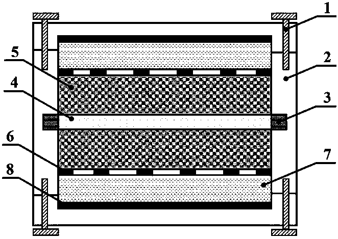
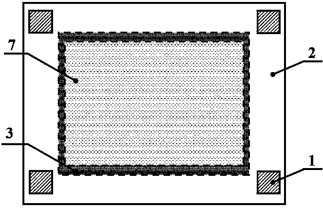
The invention discloses a quantum dot radiofluorescence effect nuclear battery, and relates to the field of nuclear energy application . The battery comprises a sealed shell, a radioactive source, a quantum dot fluorescence layer and a semiconductor photovoltaic assembly, the semiconductor photovoltaic assembly comprises a semiconductor, a front electrode and a back electrode, the radioactive source is arranged in the sealed shell, the radioactive surface of the radioactive source is covered with the quantum dot fluorescence layer, the thickness of the quantum dot fluorescence layer is less than or equal to the range of radioactive particles in the quantum dot fluorescence layer, the quantum dot fluorescence layer is covered with the front electrode of the semiconductor photovoltaic assembly, and a quantum dot fluorescence material in the quantum dot fluorescence layer is an all-inorganic perovskite. The emission wavelength of the fluorescence layer can be regulated through regulatingthe composition and the dimension of quantum dots in order to make the nuclear battery have excellent output performance.

Description

technical field [0001] The invention relates to the field of nuclear energy application, in particular to a nuclear battery with quantum dot radioluminescence effect. Background technique [0002] Nuclear batteries, also known as radioisotope batteries, use energy-carrying particles (such as alpha particles, beta particles and gamma / X-rays) released during the spontaneous decay of radioisotopes or thermal effects or light effects caused by energy-carrying particles. Electrical energy device. Because of its small size, light weight, long life, strong environmental adaptability, wide operating temperature range, and stable output power, it is used in many fields such as MEMS micro-electromechanical systems, ultra-low power devices, and automatic control systems, especially for device replacement and In the harsh environment where maintenance is difficult, nuclear batteries have great potential utilization value. [0003] In 1957, Elgin-Kidde of the United States proposed for...

Claims


Application Information

Patent Timeline
IPC IPC(8): C09K11/02C09K11/66G21H1/06
Inventor 刘云鹏陈旺汤晓斌许志恒张峥嵘
Owner NANJING UNIV OF AERONAUTICS & ASTRONAUTICS
Learn More