
MEMS viscosity-density sensor chip based on in-plane resonance and preparation method thereof

A density sensor and resonance technology, applied in the field of MEMS sensors, can solve the problems of low measurement accuracy, achieve the effect of improving quality factor, improving stability, good measurement accuracy and sensitivity

Active Publication Date: 2018-01-19
XI AN JIAOTONG UNIV
View PDF6 Cites 5 Cited by
  • Summary
  • Abstract
  • Description
  • Claims
  • Application Information

AI Technical Summary

Problems solved by technology

[0004] In order to solve the problems existing in the prior art, the object of the present invention is to provide a MEMS viscosity sensor chip based on in-plane resonance and a preparation method thereof. The pressure film damping in between is replaced by sliding film damping, which reduces the damping force on the viscosity sensor chip in the fluid environment, improves the quality factor of the sensor chip and has a higher resonance frequency, and improves the measurement of viscosity and density by the viscosity sensor chip. Measurement performance such as accuracy and sensitivity can effectively solve the technical problem of low measurement accuracy of high-viscosity fluids in the existing technology.

Method used


Image

  • MEMS viscosity-density sensor chip based on in-plane resonance and preparation method thereof
  • MEMS viscosity-density sensor chip based on in-plane resonance and preparation method thereof
  • MEMS viscosity-density sensor chip based on in-plane resonance and preparation method thereof

Examples


Embodiment Construction

[0047] The present invention will be described in further detail below in conjunction with the accompanying drawings and through examples.

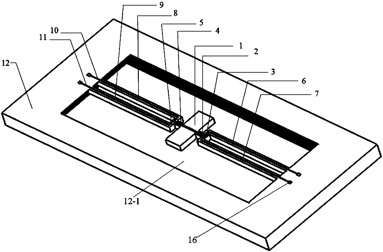
[0048] Such as figure 1 As shown, the MEMS viscosity sensor chip based on in-plane resonance of the present invention is characterized in that it includes a silicon substrate 12, a silicon micro-resonant beam structure and wires, and a window 12-1 is provided on the silicon substrate 12, and the silicon micro-resonant beam structure Set in the window 12-1 and connected to the window 12-1, the silicon substrate 12 is single crystal silicon;

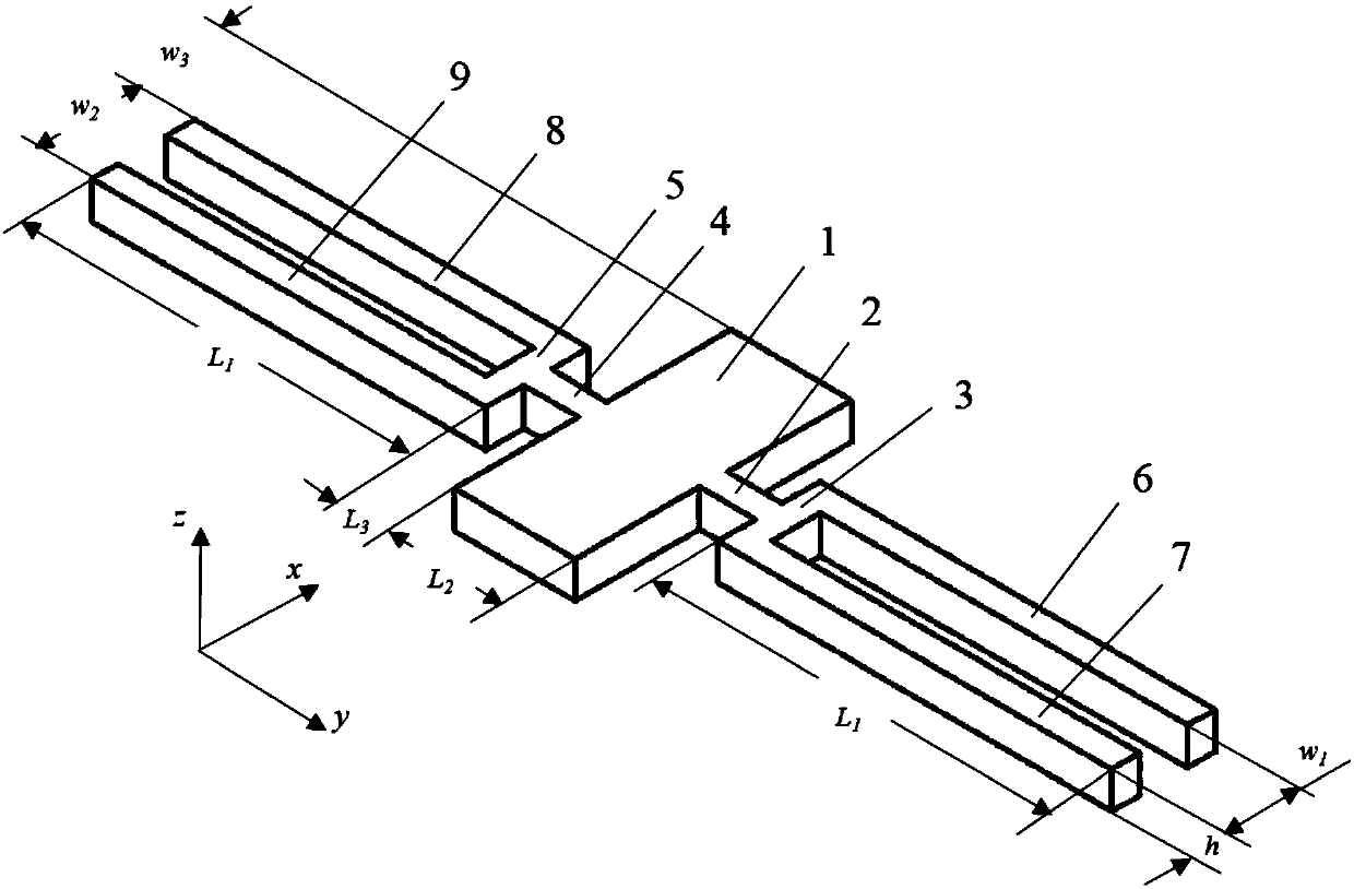
[0049] The silicon micro-resonant beam structure includes a vibrator 1, elastic connecting beams, elastic fixed beams and wires;

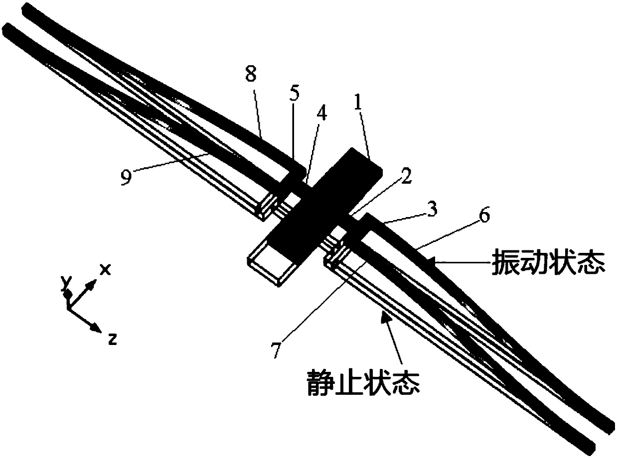
[0050] The elastic connecting beam includes the first elastic connecting beam 2, the second elastic connecting beam 3, the third elastic connecting beam 4 and the fourth elastic connecting beam 5; the elastic fixed beam includes the first elastic fixed beam 6, the second ...


PUM

PropertyMeasurementUnit
Lengthaaaaaaaaaa
Widthaaaaaaaaaa
Thicknessaaaaaaaaaa

Abstract

The invention discloses an MEMS viscosity-density sensor chip based on in-plane resonance and a preparation method thereof. The MEMS viscosity-density sensor chip comprises a silicon substrate and a silicon micro resonant beam structure, wherein the silicon micro resonant beam structure comprises a middle oscillator, elastic connecting beams and elastic clamped beams; the elastic connecting beamsand the elastic clamped beams are arranged at two sides of the oscillator; two mutually vertical connecting beams at each side of the oscillator form a T-shaped beam structure; the oscillator, and theelastic connecting beams and elastic clamped beams at the two sides of the oscillator are respectively provided with two leads; the two leads are distributed along the length direction of the oscillator in parallel and are respectively used for circulating sinusoidal alternating current of a certain frequency and induced electromotive force generated by detection, obtaining a resonant frequency of the silicon micro resonant beam in measured fluid according to the output amplitude of the induced electromotive force when the silicon micro resonant beam is in a resonant state and realizing measurement of the viscosity and the density of the fluid through the resonant frequencies and quality factors of the silicon micro resonant beam in the different fluid. The MEMS viscosity-density sensor chip utilizes methods of electric magnetization and electromagnetic testing to realize accurate measurement of the viscosity and the density of the fluid based on an in-plane vibration principle.

Description

technical field [0001] The present invention relates to the field of MEMS (Micro Electromechanical Systems, micro-mechanical electronic systems) sensors, more specifically, to a MEMS viscosity sensor chip based on in-plane resonance and a preparation method thereof. Background technique [0002] With the development of MEMS (Micro Electromechanical Systems, micro-mechanical electronic systems) technology, MEMS viscosity sensor is a multifunctional sensor that can measure fluid viscosity and density at the same time. It has the advantages of miniaturization, integration, low power consumption and accuracy. The advantages of high density make it widely used in many fields such as industry, medical treatment, chemical industry and biology. For the viscosity sensor based on the resonance principle, according to the different vibration modes of the resonant device in the fluid, it can be divided into out-of-plane vibration and in-plane vibration. For out-of-plane vibration, there...

Claims


Application Information

Patent Timeline
IPC IPC(8): B81B3/00B81C1/00
Inventor 赵立波黄琳雅蒋维乐胡英杰王久洪李支康苑国英赵玉龙蒋庄德
Owner XI AN JIAOTONG UNIV
Learn More