
Vacuum degreasing sintering furnace

A technology of vacuum degreasing and sintering furnace, which is applied in the direction of furnace, furnace type, lighting and heating equipment, etc., can solve the problems of low production efficiency, and achieve the effect of high production efficiency and high marriage rate.

Pending Publication Date: 2018-01-16
NINGBO HIPER VACUUM TECH CO LTD
View PDF0 Cites 7 Cited by
  • Summary
  • Abstract
  • Description
  • Claims
  • Application Information

AI Technical Summary

Problems solved by technology

It can be seen that the production efficiency of the traditional vacuum degreasing and sintering integrated furnace is low

Method used


Image

  • Vacuum degreasing sintering furnace
  • Vacuum degreasing sintering furnace
  • Vacuum degreasing sintering furnace

Examples


Embodiment 1

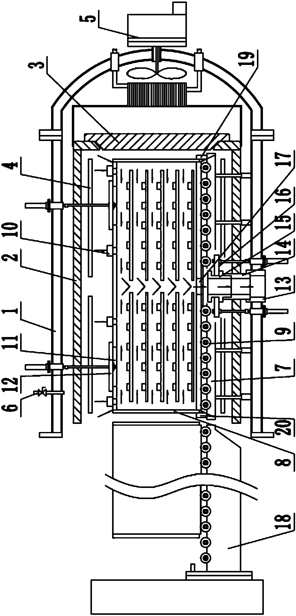
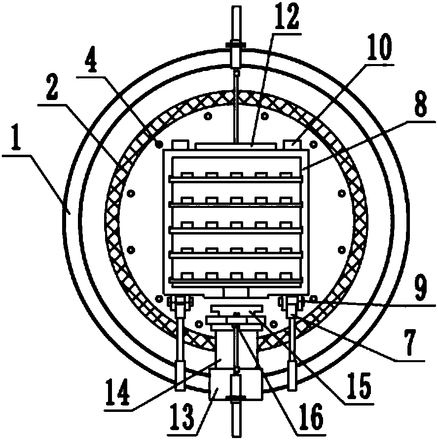
[0033] Embodiment 1: as Figure 1-2As shown, this embodiment provides a vacuum degreasing sintering furnace, including a furnace body 1 and a heat insulation cylinder 2 and an insulation door 3 arranged in the furnace body 1, the heat insulation cylinder 2 and the heat insulation door 3 are made of heat insulation materials In this way, the insulation door 3 is arranged on the two ends of the heat insulation cylinder 2, and the insulation door 3 is connected with the furnace door as a whole, which can be opened and closed. The inside of the heat-insulating cylinder 2 is provided with a heating body 4, and the heating of the heating body 4 can radiate the material box 8 to heat up. One end of body of heater 1 is hinged with furnace door (not in figure 1 In drawing), the other end of the furnace body 1 is also hinged with a furnace door, and a cooling system 5 is provided on the furnace door. The cooling system 5 includes a fan, an impeller and a cooler, the fan is arranged on...

Embodiment 2

[0039] Embodiment 2: as Figure 5 As shown, the present embodiment provides a vacuum degreasing sintering furnace, including a first furnace body 22, a second furnace body 23 and a third furnace body 24 connected end to end in sequence, the first furnace body 22 is used to perform a degreasing process, and the second furnace body 22 is used to perform a degreasing process. The second furnace body 23 is used for performing the sintering process, and the third furnace body 24 is used for performing the cooling process.

[0040] The front end of the first furnace body 22 and the tail end of the third furnace body 24 are hinged with a furnace door 25, which can be opened to facilitate the loading and unloading of the material box 8 by the skip truck 18. The inside of the second furnace body 23 is provided with a heat-insulating cylinder 2, and the inside of the heat-insulating cylinder 2 is provided with a heating body 4. The two ends of the second furnace body 23 are movably conn...


PUM


Abstract

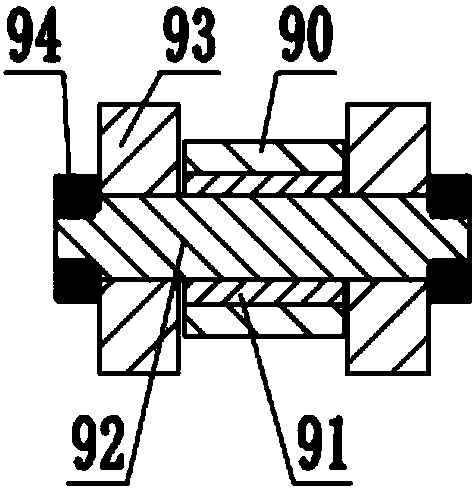
The invention discloses a vacuum degreasing sintering furnace. The furnace comprises a furnace body, and a thermal insulation cylinder and thermal insulation doors which are arranged inside the furnace body, wherein the thermal insulation doors are arranged at the two ends of the thermal insulation cylinder, and a heating body is arranged inside the thermal insulation cylinder; furnace doors are hinged to the two ends of the furnace body, any one of the two furnace doors is provided with a cooling system, a gas inlet pipe is arranged on the furnace body and is communicated with a gas source; the furnace body is connected with a graphite guide rail through a stand column, the graphite guide rail is used for supporting and conveying a work bin and is provided with a plurality of rolling needle bearings, and the work bin can move on the graphite guide rail; a gas inlet valve and a cooling hole are arranged on the work bin, and the cooling hole can be closed by a movable upper cover on thefurnace body; a gas exhaust flange is arranged at the lower part of the furnace body, is communicated with a vacuum pump, and is connected with a lower degreasing pipe and an upper degreasing pipe insequence, and the upper degreasing pipe is driven by a lifting mechanism to move in the lower degreasing pipe and is communicated or separated from a gas discharging hole of the work bin. The vacuumdegreasing sintering furnace has the advantage of high production efficiency.

Description

technical field [0001] The invention relates to the technical field of industrial furnaces, in particular to a vacuum degreasing sintering furnace. Background technique [0002] Sintered products are usually placed in a material box and fired in a sintering furnace. The material box (also called muffle) is made of graphite and is a very important device in a vacuum degreasing and sintering integrated furnace. The reason why the material box is used to wrap the product (processing object) is that its heat conduction effect is very good, the heat loss is very small, and it can evenly ensure that the temperature of each place in the material box is consistent. When the heating body is heated, the temperature passes through radiation. Conducted to the material box, the temperature of the material box rises, the temperature of the material box is transmitted to the ceramic plate, and then transmitted to the product through the ceramic plate, the conduction temperature is very uni...

Claims


Application Information

Patent Timeline
Patent Type & Authority Applications(China)
IPC IPC(8): F27B9/04F27B9/12F27B9/26F27B9/30
Inventor 刘鹏徐文立胡芳
Owner NINGBO HIPER VACUUM TECH CO LTD
Learn More