Sealing device

A technology of sealing device and sealing ring, which is applied in the direction of engine sealing, engine components, mechanical equipment, etc., can solve the problems of unfavorable unit economic optimization, short service life, etc., and achieve the purpose of increasing service life, reducing energy loss, and improving economic operation Effect

Active Publication Date: 2018-01-09
HAMMELMANN MASCHFAB
View PDF7 Cites 0 Cited by
  • Summary
  • Abstract
  • Description
  • Claims
  • Application Information

AI Technical Summary

Problems solved by technology

However, this is not conducive to economically optimized operation of the unit
[0005] This also includes the fact that high leaks cause wear and tear due to erosion of the components involved, resulting in a relatively short service life and the resulting repair and downtime costs

Method used


Image

  • Sealing device
  • Sealing device
  • Sealing device

Examples


Embodiment Construction

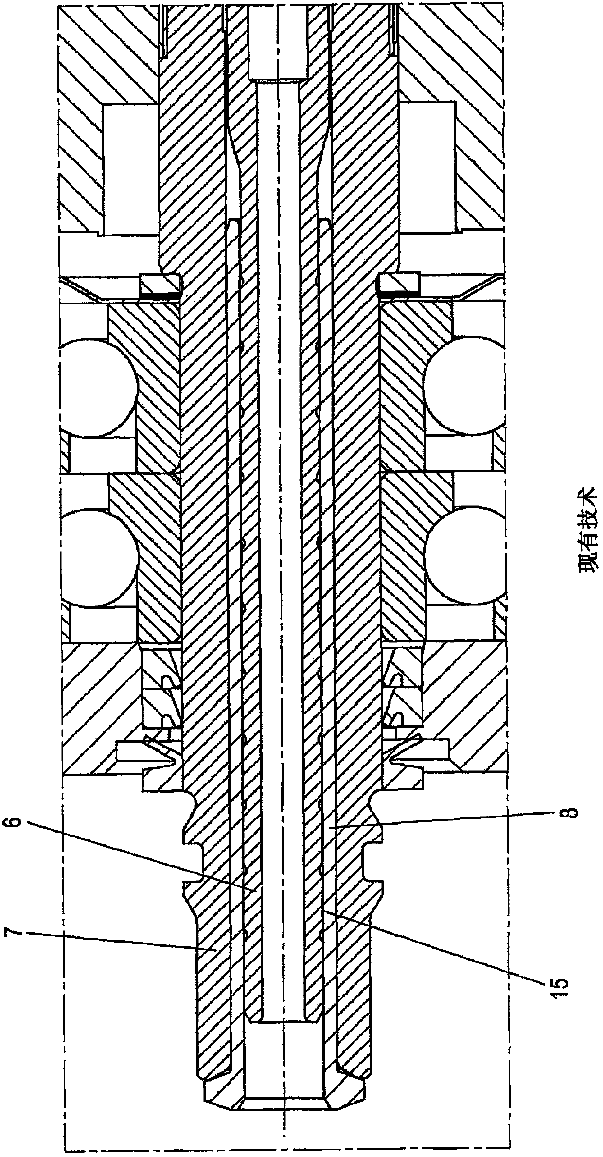
[0028] figure 1 shows a sealing device according to the prior art with an inner body 6 designed as a sleeve, an intermediate bush 8 which surrounds the inner body 6 and is mounted in an outer sleeve 7 by forming a gap seal, Therein an annular gap 15 is formed between the inner body 6 and the intermediate bushing 8 . With this design, the pressure of the fluid to be sealed causes the sleeve to widen, resulting in increased leakage.

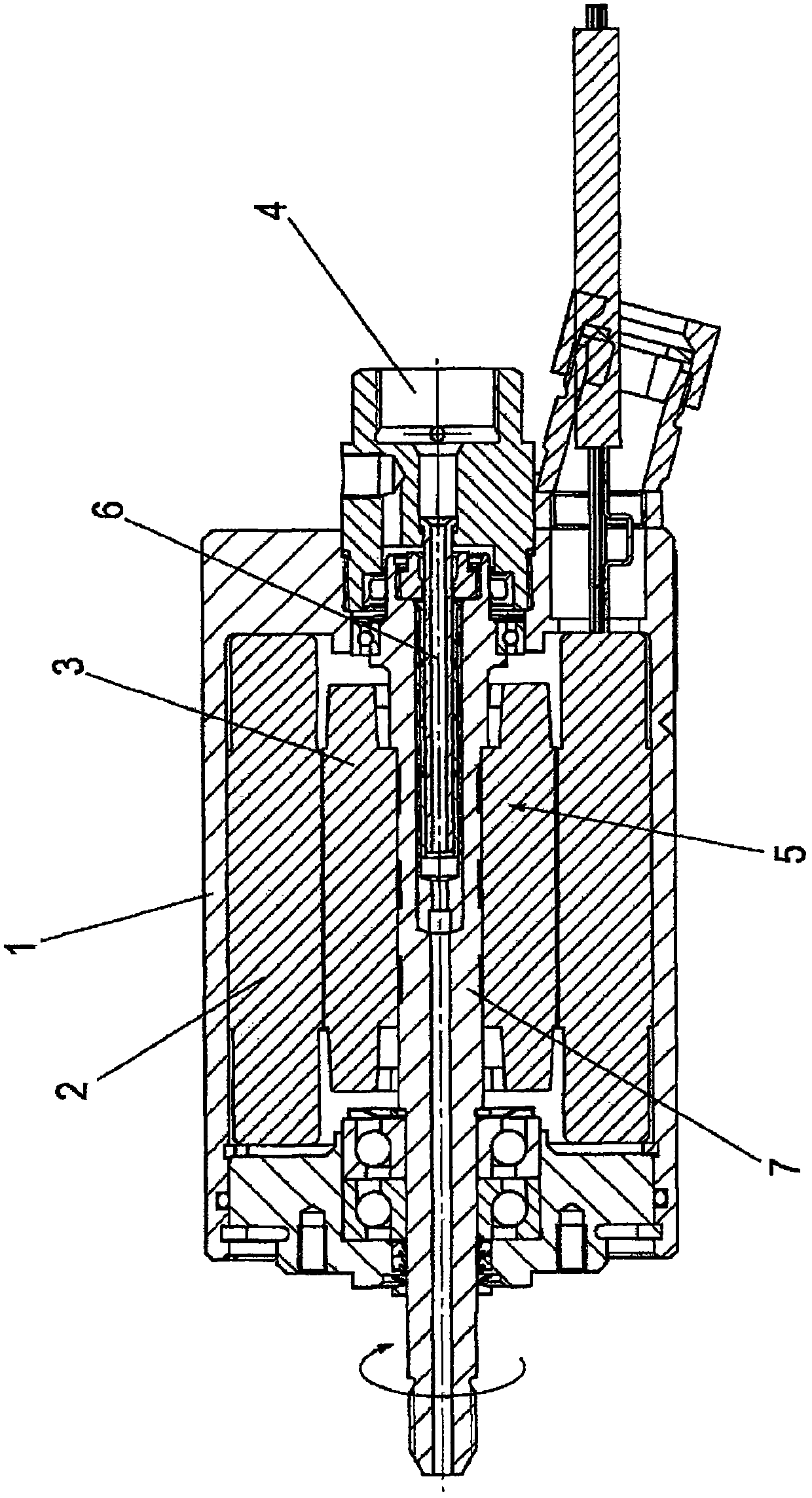
[0029] figure 2 An electric rotary drive for a hydraulic tool is shown having a housing 1, a stator 2 mounted in a rotationally fixed manner in the housing 1, and a rotor 3 in which an outer sleeve 7 is held in a rotationally fixed manner, Fluid at high pressure (>2000 bar) can be fed therethrough via the fluid connection 4 .

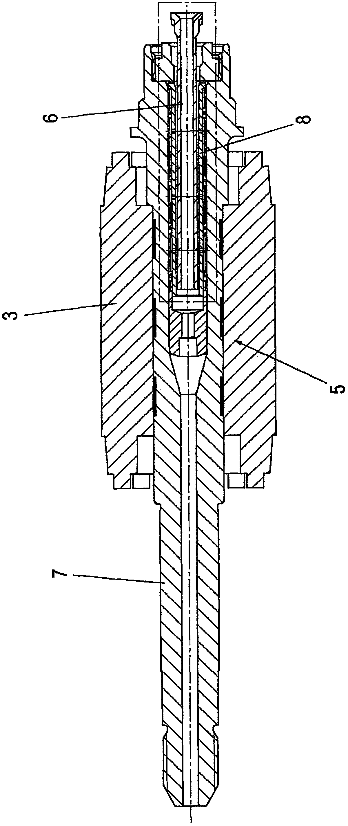
[0030] The outer sleeve 7 is part of the sealing device 5 according to the invention, the outer sleeve 7 can be placed in Figure 3-6 It can be seen more clearly in the enlarged view of .

[0031] The inner body 6 is m...


PUM


Abstract

A sealing device comprising an intermediate bushing (8), which is located between an outer sleeve (7) and an inner member (6) mounted therein so as to be movable relative thereto and which forms a gapseal, is designed in such a way that chambers (9) that can be filled with a pressurized fluid are provided between the intermediate bushing (8) and the adjacent outer sleeve (7).

Description

technical field [0001] The invention relates to a sealing arrangement according to the preamble of claim 1 . Background technique [0002] Such sealing means are especially used in situations where the unit operates at high fluid pressures (200-4000 bar). [0003] Due to the extreme operating conditions there, low-friction gap seals are used to seal parts that can move relative to each other, ie according to the type arranged between a cylindrical inner body and an outer sleeve, said gap seal has an intermediate lining An intermediate sleeve, preferably composed of non-ferrous metal, is arranged between the wall of the bore of the outer sleeve and the inner body. [0004] In this case, system-induced leakage is accepted, however, this results in considerable energy loss. Thus, in known seals optimized for the system, for example a leakage rate of about 600 ml / min is obtained at a fluid pressure of 2000 bar and a leakage rate of about 1200 ml / min is obtained at a fluid pres...

Claims


Application Information

Patent Timeline
Patent Type & Authority Applications(China)
IPC IPC(8): F16J15/00
CPCF16J15/002F16J15/006F16J15/406F16J15/441
Inventor 雷尼·内勒马丁·奥伯沙伊特格拉尔德·舒布林
Owner HAMMELMANN MASCHFAB
Why Eureka
Try Eureka