Hydraulic system for deep ocean operation type underwater robot
An underwater robot and hydraulic system technology, applied in the field of hydraulic system, can solve the problems of hydraulic pump unable to adjust output flow, large overflow loss, low system efficiency, etc. Good maneuverability
- Summary
- Abstract
- Description
- Claims
- Application Information
AI Technical Summary
Problems solved by technology
Method used
Image
Examples
Embodiment 1
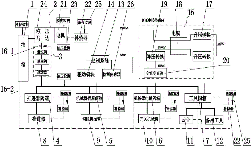
[0037] Implementation 1: If figure 1 As shown, a hydraulic system of a deep-sea operation underwater robot includes a fuel tank 1, a power source 2, a hydraulic component 3, a thruster valve box 4, a mechanical arm servo valve box 5, a mechanical arm solenoid valve box 6, and a tool valve box 7 , propeller 8, servo mechanical arm 9, switch mechanical arm 10, hydraulic platform 11, spare tool 12, control system 13, drive module 14 and high-voltage electric conversion system 15, described power source 2 will be in the fuel tank 1 The hydraulic oil is sucked out and sent to the propeller valve box 4, the mechanical arm servo valve box 5, the mechanical arm solenoid valve box 6 and the tool valve box 7 sequentially through the hydraulic element 3 and the oil supply pipeline 16-1. , servo mechanical arm 9 and switch mechanical arm 10 establish communication with propeller valve box 4, mechanical arm servo valve box 5 and mechanical arm electromagnetic valve box 6 successively, and ...
Embodiment 2
[0048] Implementation 2: If figure 1 As shown, the high-voltage power conversion system 15 includes a step-up converter 17, a high-voltage cable 18, a step-down converter 19 and an AC-to-DC power supply 20. The power conversion system is divided into two branches, and a step-up converter 17 is installed on each branch, and one of the branches of the power supply is connected to the power source 2 through the step-up converter 17 and the high-voltage cable 18, thereby providing power source 2 Power supply; another branch of the power supply is connected to the step-down converter 19 through the step-up converter 17 and the high-voltage cable 18, and the step-down converter 19 is electrically connected to the control system 13 through the AC-to-DC power supply, and then the control system 13 powered by.
Embodiment 3
[0049] Implementation 3: If figure 1 As shown, the power source 2 includes a hydraulic motor 24 and a motor 21, the motor 21 is an AC motor, and the AC motor drives the hydraulic motor 24 to draw hydraulic oil from the oil tank 1 and transmit the hydraulic oil to each hydraulic actuator go. In such a configuration, the power source includes an AC motor and a hydraulic motor, and the AC motor drives the hydraulic motor to draw hydraulic oil from the oil tank and deliver the hydraulic oil to various hydraulic actuators.
PUM
 Abstract
Description
Claims
Application Information
 - Generate Ideas
- Intellectual Property
- Life Sciences
- Materials
- Tech Scout
- Unparalleled Data Quality
- Higher Quality Content
- 60% Fewer Hallucinations
Browse by: Latest US Patents, China's latest patents, Technical Efficacy Thesaurus, Application Domain, Technology Topic, Popular Technical Reports.
© 2025 PatSnap. All rights reserved.Legal|Privacy policy|Modern Slavery Act Transparency Statement|Sitemap|About US| Contact US: help@patsnap.com


