
Laser additive texturing method

A laser material addition and texturing technology, which is applied in the field of material surface processing, can solve the problems of unsatisfactory textured appearance and excessive roll roughness attenuation, so as to improve the surface topography structure, enhance wear resistance and roughness The effect of retention and high hardness

Inactive Publication Date: 2017-12-26
BAOSHAN IRON & STEEL CO LTD
View PDF9 Cites 4 Cited by
  • Summary
  • Abstract
  • Description
  • Claims
  • Application Information

AI Technical Summary

Problems solved by technology

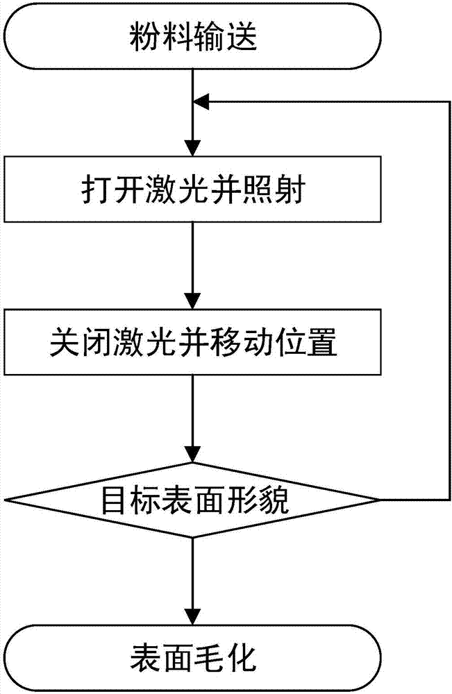
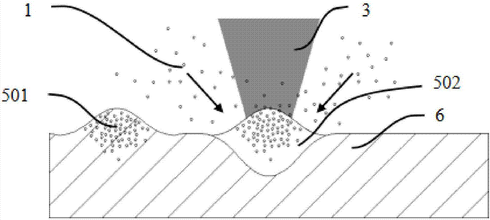
[0009] The main purpose of the present invention is to solve the problems of unsatisfactory textured appearance and excessively fast decay of roll roughness in the traditional roll texturing technology, and propose a new type of environmentally friendly laser additive texturing technology, which uses laser melting The method of depositing powder forms a series of uniform and dense fusion points on the surface of the base material to realize the surface texture of the base material, and the textured points have higher hardness than the base material

Method used


Image

  • Laser additive texturing method
  • Laser additive texturing method
  • Laser additive texturing method

Examples


Embodiment 1

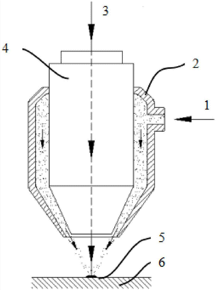
[0047] See attached figure 2, the selected powder 1 is WC, Co composite powder, the mass fraction ratio is 9:1, and the particle size is about 0.1-0.3 μm. The laser head 4 and the powder feeding nozzle 2 have a coaxial structure. The powder 1 is transported to the laser head 4 through the auxiliary nitrogen gas, and then sprayed out from the conical nozzle around the laser head 4, and gathers at the laser focus. The minimum convergence diameter It is about 100μm, the injection speed of the powder is about 15m / s, and the injection amount is about 2.5g / min. The power of the laser is 200W, the pulse frequency is 22kHz, and the spot diameter after focusing is about 80μm. Base material 6 is a common Cr5 forged roll. The focal length of the laser focusing lens is 250mm, and its focal point after focusing is consistent with the point where the powder material converges. The roll is installed on the machine tool to rotate at a speed of 250rpm. The laser head is installed on the to...

Embodiment 2

[0051] See attached Figure 4 , The selected powder is WC, Cr, Fe mixed powder, the mass fraction ratio is 6:3:1, and the particle size is about 0.2-2 μm. The laser head and the powder feeding nozzle are of paraxial structure, the minimum diameter of the powder converging is 80 μm, and other parameters are consistent with the embodiment.

[0052] According to the measurement, the diameter of the textured boss obtained under this parameter is between 80 and 120 μm, the height of the textured boss is between 5 and 8 μm, the surface roughness of the texturized roll is about 2.01 μm, and the textured point The hardness of the roll is about HV920, and the hardness of the roll surface in the untextured area is about HV320.


PUM

PropertyMeasurementUnit
Diameteraaaaaaaaaa
Heightaaaaaaaaaa
Diameteraaaaaaaaaa

Abstract

The invention discloses a laser additive texturing method. The laser additive texturing method comprises the following steps of: S1, conveying a powdery material to the surface of a base material; and S2, irradiating the powdery material with laser on a conveying point of the powdery material to fuse the powdery material and the base so as to form a protruding fusing point, moving the conveying point of the powdery material and a laser irradiating point to form a series of fusing points on the surface of the base to achieve a texturing effect of the surface of the base. According to the laser additive texturing method disclosed by the invention, the surface morphology and structure of the base material are improved effectively, and the wear resistance and roughness retentivity of the base material are enhanced.

Description

technical field [0001] The invention relates to a surface roughening technology in the technical field of material surface processing, and more particularly relates to a laser-added material roughening technology. Background technique [0002] Steel plates with rough surfaces can store lubricating oil during stamping. The ideal surface morphology of steel plates should be composed of closed independent "small oil tanks", which can ensure that the oil lubrication state is maintained between the steel plate and the mold interface, and at the same time produce a certain amount of oil. The hydrostatic effect can reduce friction. The roughness of the steel plate surface comes from the transfer of the roll. Therefore, the ideal roll surface topography should be composed of individual small bosses. [0003] Common roll texturing techniques include blasting (spray) shot texturing, EDM texturing, laser texturing, electron beam texturing, chrome plating texturing and other methods. ...

Claims


Application Information

Patent Timeline
IPC IPC(8): B23K26/352B23K26/0622
CPCB23K26/0622B23K26/3584
Inventor 陈孝明李山青全基哲
Owner BAOSHAN IRON & STEEL CO LTD
Learn More