
A test device and method for dynamic bending resistance of automobile side pillars hitting key parts

A test device, a technology on the side of the car, which is applied to the design of the test method for the dynamic bending resistance of auto parts, and the field of the test device for the dynamic bending resistance of the key parts of the automobile side pillar, which can solve the problems of high resource consumption and long development cycle. , to achieve the effect of low test cost, low cost and less interference factors

Active Publication Date: 2020-03-24
CHERY AUTOMOBILE CO LTD
View PDF5 Cites 0 Cited by
  • Summary
  • Abstract
  • Description
  • Claims
  • Application Information

AI Technical Summary

Problems solved by technology

[0005] The purpose of the present invention is to propose a test device and method for the dynamic bending performance of automobile side pillar bump key parts, so as to overcome the resource-intensive use of the whole vehicle collision test in the current automobile side pillar bump safety performance development. , The defect of long development cycle, so as to optimize the design of key parts more accurately and efficiently

Method used


Image

  • A test device and method for dynamic bending resistance of automobile side pillars hitting key parts
  • A test device and method for dynamic bending resistance of automobile side pillars hitting key parts
  • A test device and method for dynamic bending resistance of automobile side pillars hitting key parts

Examples


Embodiment 1

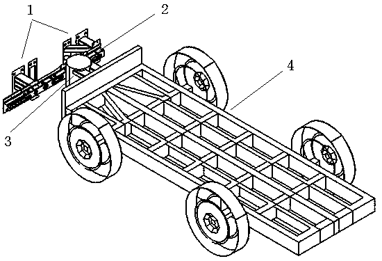
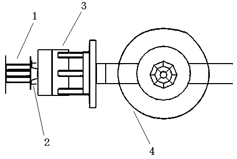
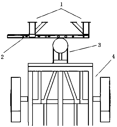
[0032] Such as figure 1 , 2, 3, the test device of the dynamic bending performance of the automobile side pillar bump key part of the present invention comprises a bracket assembly 1 installed on the rigid wall for fixing the test piece 2 and for applying dynamic impact force to the test piece 2 collision structure. Bracket assembly 1 includes a left bracket and a right bracket. The left bracket consists of a left bracket body and a left bracket connecting part arranged at the front end of the left bracket body. The right bracket consists of a right bracket body and a right bracket connecting part arranged at the front end of the right bracket body. The collision structure includes the traction trolley 4 and the collision part 3 arranged at the front end of the traction trolley 4 . The dynamic impact test is performed on the specimen 2 fixed on the bracket assembly 1 through the collision structure, which can simulate the bending deformation of the specimen 2 under high-spee...


PUM


Abstract

The invention discloses a device and method for testing dynamic bending resistance performance of key parts in an automobile side post impact in order to overcome defects of large resource consumption and long development cycle caused by complete vehicle crash tests which are generally adopted in safety performance development for automobile side post impact currently. The testing device comprises a support assembly installed on a rigid wall for fixing a testing member and a collision structure applying a dynamic impact on the testing member. The device and method for testing the dynamic bending resistance performance of the collision key parts of the automobile side column can perform a dynamic impact test on the testing member installed on the support assembly through the collision structure, can simulate a bending resistance performance of the testing member under a high-speed impact, wherein the deformation speed of the testing member accords with that of the testing member in the integral automobile test, and thus can more accurately and efficiently perform an optimization design on the testing member. Furthermore, the support assembly and the collision structure are wide in universality, simple in structure, low in cost, easy to set up, easy to install and dismount, and can be repeatedly used and tested for many times.

Description

technical field [0001] The invention belongs to the technical field of automobile safety design, and relates to the design of a test method for the dynamic bending resistance performance of automobile parts. Specifically, the present invention relates to a testing device and method for the dynamic bending resistance performance of the automobile side pillar bump key component. Background technique [0002] The side pillar impact of a car is an important crash safety test item for examining the side impact performance of a car in addition to the side impact. At present, the side pillar impact is a routine test item in European, American, Latin and other national regulations and automobile evaluation regulations, and it is likely to be introduced into C-NCAP or relevant Chinese regulations in the future. Therefore, whether it is to meet the export needs of Chinese brand cars or to prepare for future domestic regulations, the impact performance of the side pillar of the car is...

Claims


Application Information

Patent Timeline
Patent Type & Authority Patents(China)
IPC IPC(8): G01M17/007
CPCG01M17/0078
Inventor 肖海峰董金富张迎军
Owner CHERY AUTOMOBILE CO LTD
Learn More