Double-cavity furnace
The technology of a furnace body and a three-way pipe is applied in the field of double-chamber furnaces, which can solve the problems of restriction of popularization of double-chamber furnaces, difficult temperature adjustment, and inflexible use, etc., and achieve the effect of increasing energy utilization rate.
- Summary
- Abstract
- Description
- Claims
- Application Information
AI Technical Summary
Problems solved by technology
Method used
Image

Examples
Embodiment 1
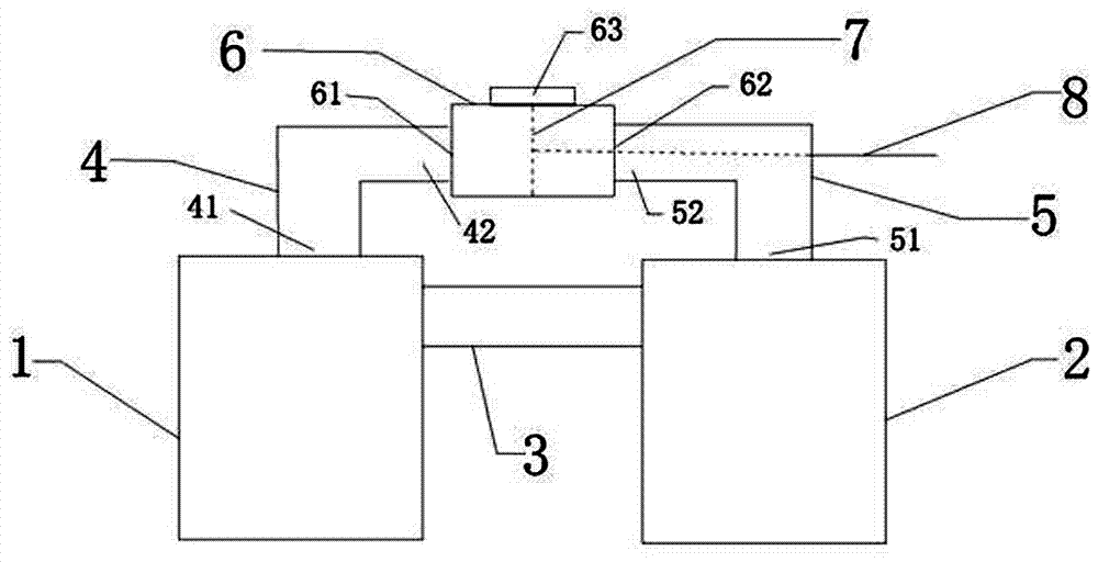
[0039] Such as figure 1 , figure 2 As shown, the double-chamber furnace of the present invention includes a first furnace body 1, a second furnace body 2, a communication pipe 3, a first smoke exhaust pipe 4, a second smoke exhaust pipe 5, a tee pipe 6, a control valve 7 and an operating Rod 8, the three-way pipe 6 is a hollow pipe integrally formed with a horizontal passage and a vertical passage, and the two ends of the horizontal passage of the three-way pipe 6 form a first communicating nozzle 61 and a second communicating nozzle 62, so The vertical passage of the three-way pipe 6 forms a third communication nozzle 63, the furnaces of the first furnace body 1 and the second furnace body 2 are communicated by the communication pipe 3, and the first smoke exhaust pipe of the first smoke exhaust pipe 4 takes in air End 41 communicates with the hearth of the first furnace body 1, the exhaust end 42 of the first exhaust pipe communicates with the first communicating nozzle 61...
Embodiment 2
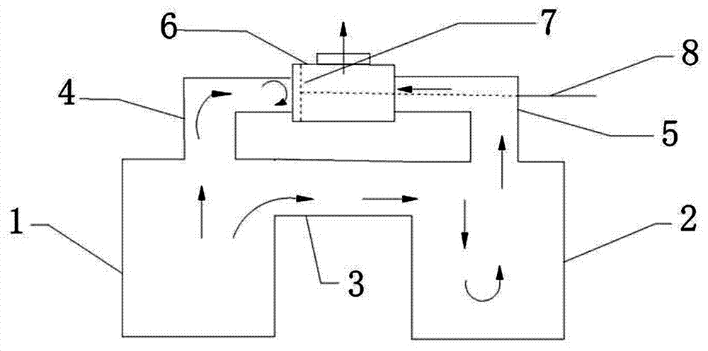
[0044] When there is fuel burning in the first furnace body 1, the user pushes / pulls the operating rod 8, and the operating rod 8 drives the control valve 7 to move, and the control valve 7 is adjusted to figure 1 The middle position of the three-way pipe 6 shown in , at this time, the exhaust end 42 of the first exhaust pipe and the exhaust end 52 of the second exhaust pipe arranged on the first exhaust pipe 4 and the second exhaust pipe 5 are both In the open state, the high-temperature exhaust gas generated by the combustion of fuel in the furnace of the first furnace body 1 is discharged through the first smoke exhaust pipe 4, and enters the second furnace body 2 through the communication pipe 3, and then enters the second furnace body 2 through the second smoke exhaust pipe 5. into the three-way pipe 6, and finally discharged into the atmosphere by the three-way pipe 6 through the third connecting nozzle 63.
[0045] In this state, the working condition of the double-chambe...
Embodiment 3
[0047] This embodiment is the same as the device used in the technical solution described in Embodiment 1, the difference is that the user can hold the handle 81 to adjust the control valve 7 to the first communication nozzle 61 of the three-way pipe 6, here When the control valve 7 closes the first smoke exhaust pipe exhaust end 42 of the first smoke exhaust pipe 4, its working condition is as follows figure 2 As shown, at this time, the second exhaust pipe exhaust end 52 of the second exhaust pipe 5 is opened, and the high-temperature exhaust gas generated in the furnace of the first furnace body 1 cannot be discharged through the first exhaust pipe 4, but can only be discharged through the connecting pipe. 3 Entering the second furnace body 2, when passing through the second furnace body 2, because the temperature of the high-temperature exhaust gas is higher than that of the second furnace body 2, according to the law of heat exchange, the high-temperature exhaust gas will...
PUM
 Abstract
Description
Claims
Application Information
 - R&D
- Intellectual Property
- Life Sciences
- Materials
- Tech Scout
- Unparalleled Data Quality
- Higher Quality Content
- 60% Fewer Hallucinations
Browse by: Latest US Patents, China's latest patents, Technical Efficacy Thesaurus, Application Domain, Technology Topic, Popular Technical Reports.
© 2025 PatSnap. All rights reserved.Legal|Privacy policy|Modern Slavery Act Transparency Statement|Sitemap|About US| Contact US: help@patsnap.com