
Energy-saving recycling tail gas treatment equipment

An exhaust gas treatment and energy-saving technology, which is applied in the field of exhaust gas treatment equipment and energy-saving recycling exhaust gas treatment equipment, can solve the problems of limited application occasions, waste, unusable heat sources, etc.

Pending Publication Date: 2017-12-22
镇江裕太防爆电加热器有限公司
View PDF3 Cites 7 Cited by
  • Summary
  • Abstract
  • Description
  • Claims
  • Application Information

AI Technical Summary

Problems solved by technology

Although these devices take into account the utilization of exhaust gas heat, the technical solution disclosed in 20120023570.3 uses natural gas for heating, and the exhaust gas only exchanges heat once, and there is still a lot of heat that is not used, which is still wasteful.
The technical solution disclosed in 201310249901.X utilizes steam heating. Due to the low processing temperature, it is only suitable for processing limited types of exhaust gases containing ozone, and its application is limited.
In the technical solution disclosed in 201710137565.6, there is only one heat storage heat exchanger, and a back-purging pipeline and a high-temperature relief valve are required during heating, so there is still a large amount of heat energy in the exhaust gas, and the back-purging pipeline is added. Undoubtedly increasing the manufacturing cost, the heat source discharged by the high temperature relief valve cannot be utilized

Method used


Image

  • Energy-saving recycling tail gas treatment equipment
  • Energy-saving recycling tail gas treatment equipment
  • Energy-saving recycling tail gas treatment equipment

Examples


Embodiment 1

[0023] The basic structure of the energy-saving recycling tail gas treatment equipment in this embodiment is as follows: Figure 2 to Figure 5 As shown, it is mainly composed of a tunnel-type electric heating furnace body 1 , a shell-and-tube exhaust gas heat exchanger 7 and a shell-and-tube exhaust gas boiler 26 . The inlet of the shell-type exhaust gas heat exchanger 7 as the exhaust gas inlet 19 to be treated passes through a tube pass composed of a set of exhaust gas heat exchange tubes 9 and passes through the 180° elbow 5, and then connects to the tunnel-type electric heating furnace body through the expansion and reduction tube 4 The inlet of 2 is heated at a lower flow rate in the furnace body. The outlet of the tunnel-type electric heating furnace body 1 passes through the reduced-diameter variable-diameter pipe and the 90° elbow 5, and then passes through the shell side of the shell-and-tube exhaust gas heat exchanger 9 to connect a group of steam heat exchange tubes...


PUM


Abstract

The invention relates to energy-saving recycling tail gas treatment equipment, and belongs to the technical field of environment protection facilities. The equipment comprises a tunnel type electric heating furnace and further comprises a shell-and-tube exhaust gas heat exchanger and a shell-and-tube tail gas boiler. An inlet of the shell-and-tube exhausts gas heat exchanger serving as the to-be-treated exhaust gas inlet is connected with an inlet of the tunnel type electric heating furnace through a tube side of the shell-and-tube exhaust gas heat exchanger. An outlet of the tunnel type electric heating furnace is connected with a tube side of the shell-and-tube tail gas boiler through a shell side of the shell-and-tube exhaust gas heat exchanger, and then gas is exhausted. The shell side of the shell-and-tube tail gas boiler communicates with a steam storage tank of an external steam conveying pipeline. According to the energy-saving recycling tail gas treatment equipment provided by the invention, heat of high-temperature exhaust gas after electric heating treatment is completed is utilized reasonably twice, a preheating effect is achieved, and decomposing and energy saving of the exhaust gas are facilitated; and heat is fully adsorbed in the steam generating process, the temperature is greatly decreased, the size is obviously reduced, accordingly energy is effectively saved, and emission is effectively reduced.

Description

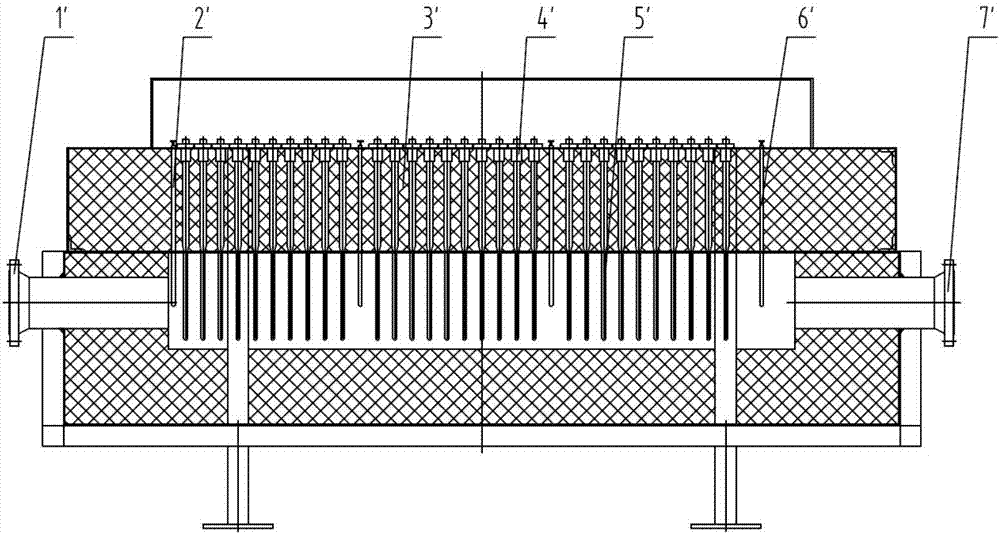
technical field [0001] The invention relates to a tail gas treatment device, in particular to an energy-saving recycling tail gas treatment device, which belongs to the technical field of environmental protection facilities. Background technique [0002] As far as the applicant knows, the typical structure of the existing waste gas treatment equipment (such as sulfur and nitric waste gas discharged from power plants; ammonia gas, hydrocarbons, chlorine compound waste gas discharged from chemical plants, etc.) is as follows: figure 1 As shown, the tunnel-type furnace body 3' is provided with an electric heating head composed of an electric heating wire 5' inserted from the insertion port 4', and a temperature measuring probe 6' is housed. When the exhaust gas to be treated enters the furnace body from the inlet port 1', the electric heating head 3' generates a high temperature of 1050 °C to directly burn the harmful components in the exhaust gas, and then enters the atmospher...

Claims


Application Information

Patent Timeline
Patent Type & Authority Applications(China)
IPC IPC(8): F23G7/06F22B1/18
CPCF22B1/1869F23G7/063
Inventor 王裕福王太峰王太祥
Owner 镇江裕太防爆电加热器有限公司
Learn More