
A nozzle that uses turboshaft engine exhaust to generate electricity

A turboshaft engine and nozzle technology, which is used in machines/engines, mechanical equipment, jet propulsion devices, etc., can solve the problems of low exhaust gas energy grade and can not meet the effective utilization of exhaust gas energy, and achieves the improvement of cycle efficiency and output power. Effect

Active Publication Date: 2019-10-08
AERO ENGINE ACAD OF CHINA
View PDF6 Cites 0 Cited by
  • Summary
  • Abstract
  • Description
  • Claims
  • Application Information

AI Technical Summary

Problems solved by technology

[0004] However, due to the low grade of energy in the tail gas emitted by the turboshaft engine, it is difficult to take effective technical measures to utilize it. Only relying on the optimized design of the geometric parameters of the nozzle can no longer meet the demand for effective utilization of exhaust energy. Therefore, there is an urgent need to Propose a new type of nozzle that can effectively utilize the exhaust energy

Method used


Image

  • A nozzle that uses turboshaft engine exhaust to generate electricity
  • A nozzle that uses turboshaft engine exhaust to generate electricity
  • A nozzle that uses turboshaft engine exhaust to generate electricity

Examples


Embodiment Construction

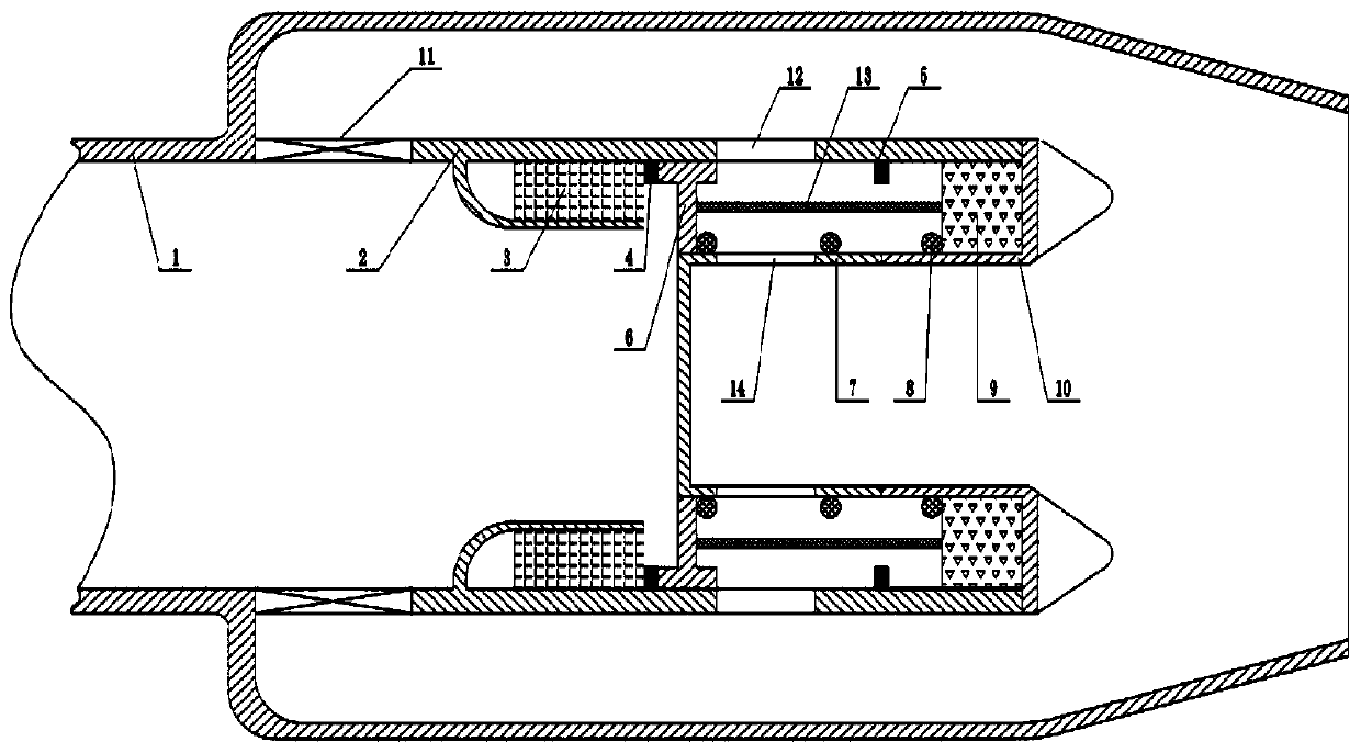
[0026] The application will be further described in detail below in conjunction with the accompanying drawings and embodiments. It should be understood that the specific embodiments described here are only used to explain relevant content, rather than to limit the present application. In addition, it should be noted that, for ease of description, only parts relevant to the present application are shown in the drawings.

[0027] It should be noted that, in the case of no conflict, the embodiments in the present application and the features in the embodiments can be combined with each other.

[0028] The structure of the spray pipe of the present application is described in detail below at first with reference to accompanying drawing:

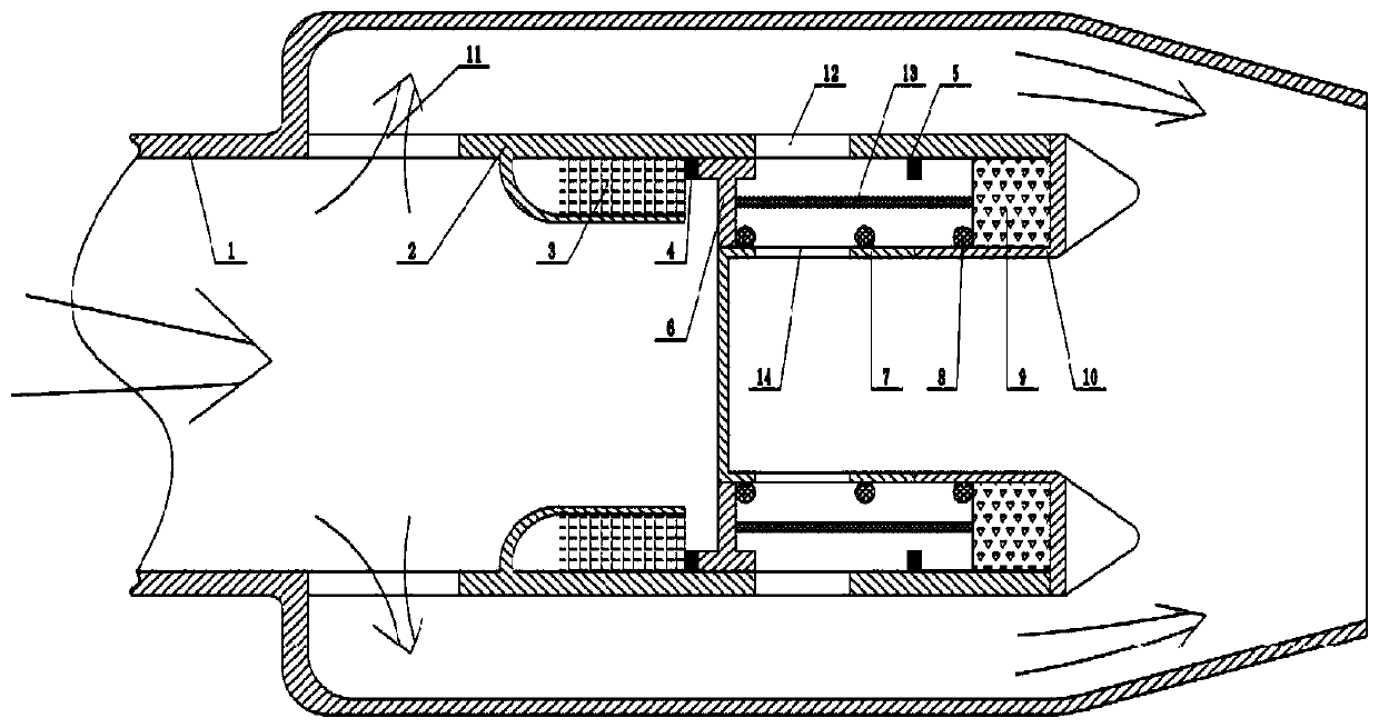
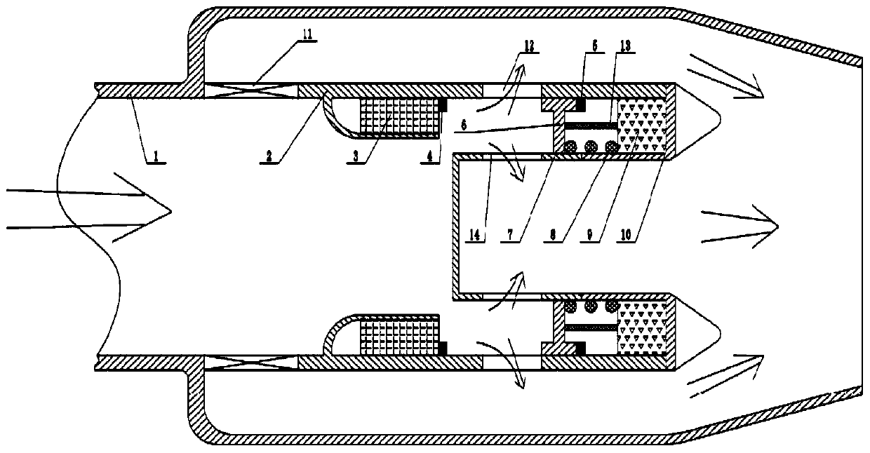
[0029] figure 1 It shows the general structure schematic diagram of an embodiment of the nozzle of the present application utilizing turboshaft engine exhaust to generate electricity. In this embodiment, the nozzle of the present application in...


PUM


Abstract

The invention provides a spray pipe for generating power through turboshaft engine tail gas. The spray pipe comprises a spray pipe outer culvert casing (1), a spray pipe inner culvert casing (2), a piston (6), a spring (8), a spring support (7), a permanent magnet (3), a connecting rod (13) and a pressure adjustment valve (11). An outer culvert channel is formed between the spray pipe outer culvert casing and the spray pipe inner culvert casing, wherein the tail gas is guided to be discharged out of a turboshaft engine through the outer culvert channel. The piston is arranged between the spraypipe inner culvert casing and the spring support and can perform reciprocating linear motion. The spring is mounted between the piston and a linear electric generator and is in the compressed state.The permanent magnet is fixed to the spray pipe inner culvert casing and generates attraction force for the piston. The connecting rod is used for enabling the piston to be connected with the linear electric generator, and thus mechanical energy generated through linear reciprocating motion of the piston is transmitted to the linear electric generator so that the linear electric generator can generate power. The pressure adjustment valve is used for conducting pressure adjustment on the tail gas of the turboshaft engine and controllably discharging the tail gas into the outer culvert channel.

Description

technical field [0001] The application relates to a nozzle for generating electricity by utilizing exhaust gas of a turboshaft engine, and belongs to the field of recovery and utilization of engine exhaust gas. Background technique [0002] Generally, the pressure of the exhaust gas discharged by the turboshaft engine is several thousand Pascals higher than the external atmospheric pressure, the velocity of the exhaust gas is about tens to more than one hundred meters per second, and the temperature of the exhaust gas is also relatively high. Usually, the tail nozzles of turboshaft engines are designed according to the principle of isentropic expansion, and simply discharge the substances discharged by the turboshaft engine into the atmosphere, resulting in waste of pressure energy, velocity kinetic energy and heat energy in the turboshaft engine exhaust. [0003] With the pursuit of continuous improvement of thermal engine cycle efficiency in engineering circles, as well as...

Claims


Application Information

Patent Timeline
Patent Type & Authority Patents(China)
IPC IPC(8): F02K1/78F01B23/10
Inventor 闫文辉朱大明苏丽媛徐金纯张常贤
Owner AERO ENGINE ACAD OF CHINA
Learn More