Aortic valve stent

A technology of aorta and valve, applied in the field of medical devices, can solve the problems of paravalvular leakage, aortic valve stent positioning problem, unresolved paravalvular leakage, limited recovery force, etc., to reduce paravalvular leakage and central Sexual reflux, avoiding the risk of vascular complications, and ensuring the effect of shaping and area

Pending Publication Date: 2017-12-22
姜正明 +1
View PDF8 Cites 4 Cited by
  • Summary
  • Abstract
  • Description
  • Claims
  • Application Information

AI Technical Summary

Problems solved by technology

The main problems of this bracket are: there is a bottleneck in the thickness of the polymer sealing unit, too thick will cause loading difficulties, and too thin will have a very limited shape recovery force, which cannot achieve the expected effect; the sealing unit used is insufficient in compliance and cannot automatically fill irregularities The concave part of the tissue ring, while the convex part of the tissue ring will compress the valve frame through the sealing unit, thereby affecting the closing shape and hemodynamics of the valve, and even leading to more serious paravalvular leakage
[0005] In summary, although various efforts have been made, the positioning problems of the existing aortic valve stents and the problems of paravalvular leakage have not been well resolved.
Moreover, all existing valve stents are only suitable for patients with aortic valve stenosis due to positioning problems, and are not suitable for patients with aortic valve insufficiency.

Method used


Image

  • Aortic valve stent
  • Aortic valve stent
  • Aortic valve stent

Examples


Embodiment Construction

[0025] The technical solutions of the present invention will be further described below in conjunction with the accompanying drawings and specific embodiments.

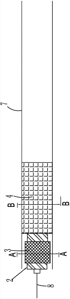
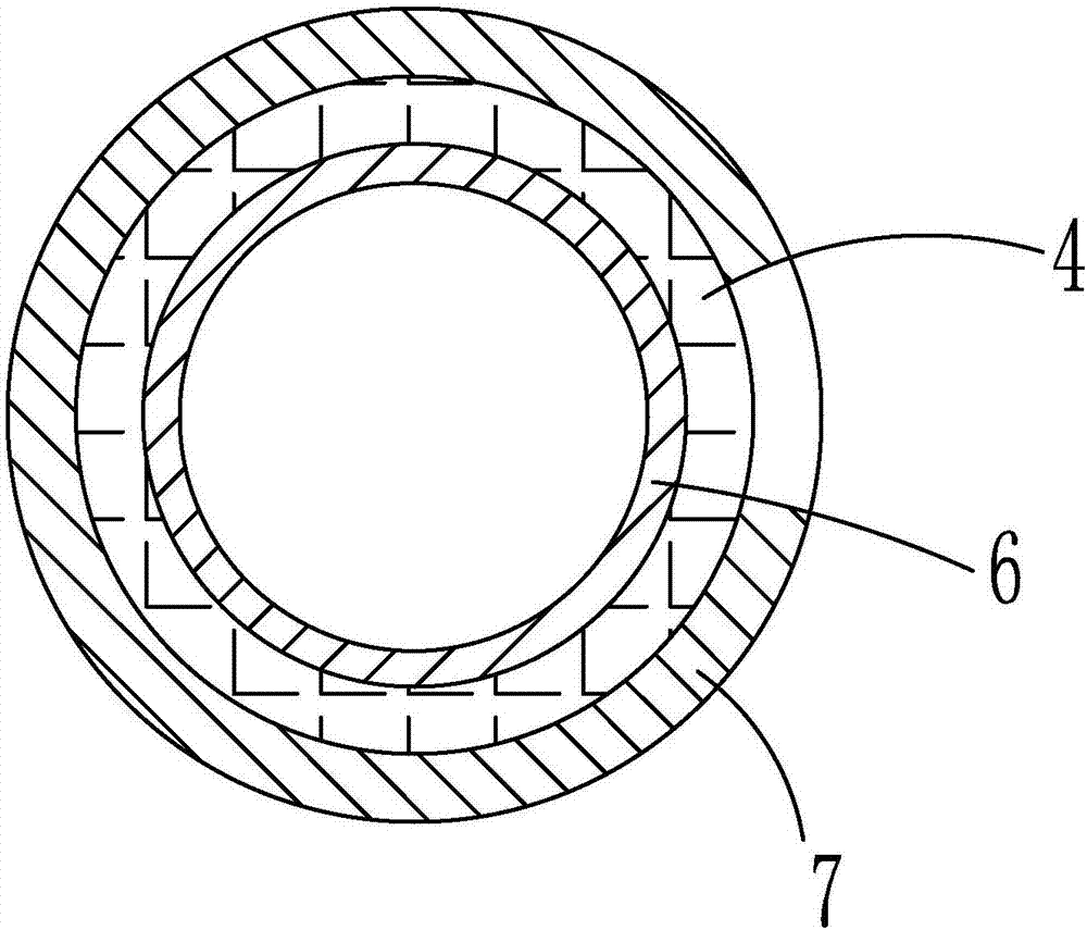
[0026] Such as figure 1 As shown, the present invention relates to an aortic valve system, which includes a stent, an artificial valve 1 connected to the stent, and an aortic valve stent delivery system.

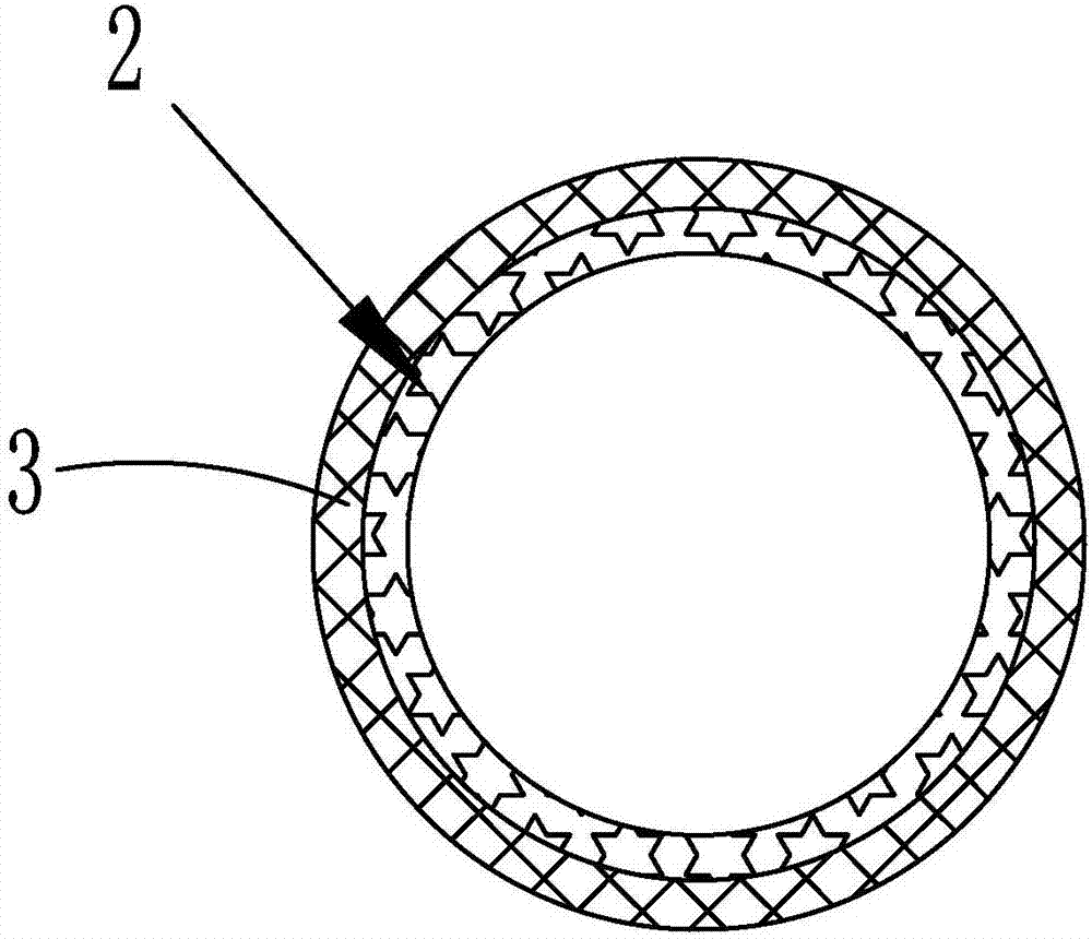
[0027] The aortic valve stent delivery system includes a pushing and releasing device for delivering the stent, and a special-shaped balloon catheter 2 arranged at the front end of the pushing and releasing device.

[0028] Special-shaped balloon catheter 2 comprises balloon 21, as attached Figure 4 and 5 As shown, the balloon 21 has a columnar connection portion 211 and a balloon expansion portion 212 communicating with the columnar connection portion 211, the columnar connection portion 211 is connected to the front end of the push release device, and the balloon 21 is designed to expand the balloon after expan...


PUM


Abstract

The invention relates to an aortic valve stent. The aortic valve stent comprises a stent body and a prosthetic valve connected to the stent body, the stent body is of a double-layer stent body and specifically comprises a balloon expanding stent body and a self-expanding stent body, the prosthetic valve is connected to the self-expanding stent body, and after the stent body is conveyed, the self-expanding stent body is located on the inner periphery of the balloon expanding stent body and tightly abuts against the balloon expanding stent body to the outer periphery; the balloon expanding stent body tightly abuts against the aortic valve of the human body to the outer periphery, and an anchoring structure is formed between the balloon expanding stent body and the self-expanding stent body. According to the stent with the prosthetic valve, through the double-layer design, the full expansion and fixation of the aortic valve are ensued, the shape and area in the stent are ensured, and meanwhile, the compliance and support strength of the stent are ensured; the occurrence of perivalvular leakage and central regurgitation is reduced, the diameter of the sheath is not increased, and the risks of vascular complications are avoided.

Description

technical field [0001] The invention belongs to the field of medical equipment, and in particular relates to an aortic valve stent. Background technique [0002] With the development of my country's aging society, the incidence of valvular degeneration in the elderly is increasing, and aortic stenosis has gradually become the most common valvular heart disease in this population. Surgical aortic valve replacement used to be the only life-prolonging treatment for patients with severe aortic stenosis, but elderly patients are often contraindicated for surgery due to advanced age, weak constitution, severe lesions, or other diseases. Statistics from developed countries show that about 1 / 3 of patients with severe aortic stenosis cannot accept traditional surgical thoracotomy because of high surgical risks or contraindications. For these high-risk patients or patients with contraindications to cardiac surgery, transcatheter aortic valve implantation can now be used as an effecti...

Claims


Application Information

Patent Timeline
IPC IPC(8): A61F2/24
CPCA61F2/2418A61F2/2436A61F2250/0065A61F2250/0069
Inventor 宋光远姜正明
Owner 姜正明
Why Eureka
Try Eureka