Excitation-fixed-frequency-triggering electric-generator voltage regulator

A generator voltage and regulator technology, which is applied to control the generator through the change of the magnetic field, control the generator, electrical components, etc., can solve the problems of poor stability, many peripheral components, high price, etc., achieve engine resistance torque balance, and extend the belt The effect of improving the service life and idling speed stability

Inactive Publication Date: 2017-12-15
佛山中锦微电科技有限公司
View PDF0 Cites 1 Cited by
  • Summary
  • Abstract
  • Description
  • Claims
  • Application Information

AI Technical Summary

Problems solved by technology

However, this kind of non-regulator dedicated chip has unstable interference and poor temperature characteristics.
[0010] Fourth, use a general-purpose comparator or operational amplifier integrated chip, such as LM158 / LM2901 / 2902 / 2903 / 2904, etc. This type of chip can form a variety of regulators in combination with discrete components designed in the periphery. The design is more flexible, but its protection The circuits are generally not perfect, and they are all non-fixed frequency excitation regulators. Some of the above disadvantages still exist, and there are many peripheral components, and the excitation stability is not good.
[0011] Fifth, the independent chip voltage regulator, this kind of regulator generally only has a plastic-encapsulated thick-film chip, and only a few noise-cancelling capacitors between the pins on the periphery. These technologies are all from foreign countries, such as the G-type multi-function voltage regulator of Denso Etc., the technology is mature and the protection is perfect. This kind of regulator is also the proprietary design of the original factory, and the price is relatively high. Generally, it is sold as a complete generator assembly, and the regulator and its chips are not marketed.
[0012] Sixth, the data control regulator has different packaging forms depending on the manufacturer, including flip chip, independent chip, single-chip microcomputer chip, etc. This type of regulator is still the original proprietary design, and the price is relatively high. The generator assembly is sold as a whole, and the regulator and its chips are not circulated in the market
[0013] In view of the above reasons, the automotive generator industry urgently needs non-data-controlled high-reliability voltage regulators with the largest market demand. Generally, mid-range and below cars, large, medium and small passenger cars, trucks, and agricultural machinery generally use non-data-controlled voltage regulators. Control type regulator, the market demand and stock of this kind of vehicle are relatively large. These voltage regulators have different designs and many types. Generally, they do not have the function of constant frequency excitation, nor the function of short circuit and overcurrent of excitation winding, and the quality of protection varies. Irregularity, poor stability, and high damage rate, which is a major technical bottleneck plaguing the automotive generator industry
There is a great demand for this type of regulator in the market. At present, there is a lack of fixed excitation frequency with relatively complete protection function, that is, a voltage regulator with fixed frequency trigger excitation. Due to the lack of circuit design with high reliability, some generators with high technical requirements cannot be used. Do not use more expensive imported chips to assemble voltage regulators or directly purchase imported generator assemblies, thus increasing the production cost of generators

Method used


Image

  • Excitation-fixed-frequency-triggering electric-generator voltage regulator
  • Excitation-fixed-frequency-triggering electric-generator voltage regulator
  • Excitation-fixed-frequency-triggering electric-generator voltage regulator

Examples


Embodiment 1

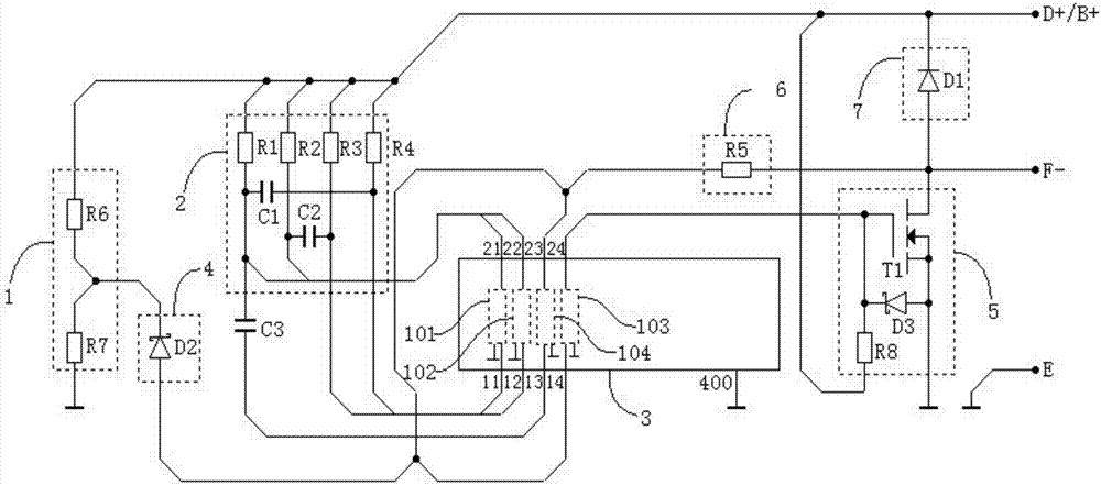
[0102] Such as figure 1 Shown is a circuit block diagram of a generator voltage regulator with constant frequency trigger excitation provided by the present invention. The generator voltage regulator includes:

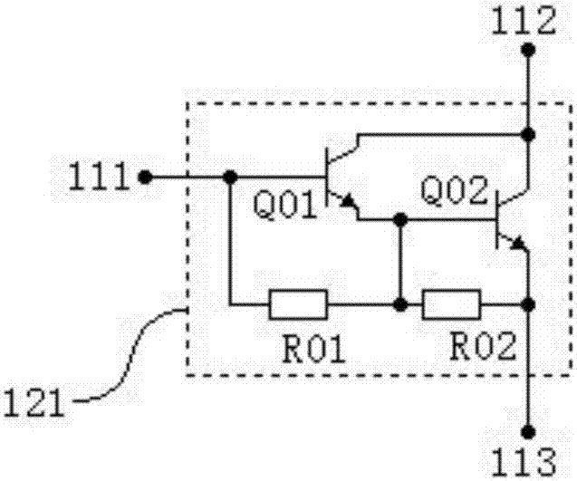
[0103] Transistor array integrated chip 3, the integrated chip can generally adopt a general-purpose transistor array integrated chip, and different crystal groups in the chip form a fixed frequency oscillation circuit, a pulse shaping circuit and a power trigger circuit with peripheral components respectively; the chip is required to have at least Four crystal groups, and the four crystal groups are negatively grounded. Each crystal group is a voltage or current amplification element composed of several transistors. The crystal group can be a composite transistor structure, and the number of crystal groups can be more than four, such as ULNxxxx A series of transistor array integrated chips generally have 7-8 crystal groups (composite transistors). Such an array integr...

Embodiment 2

[0139] The embodiment of the present invention further provides a constant frequency trigger excitation generator voltage regulator, including the aforementioned figure 2 The generator voltage regulator shown as the basic structure also includes: a phase identification processing unit and a charging indicator control unit to form a multifunctional generator voltage regulator;

[0140] The input end of the phase identification processing unit is used to connect with the phase terminal P of the generator, the output end of the phase identification processing unit is connected to the input end of the electric indicator L control unit, and the output end of the electric indicator L control unit is used to control the generator charging indicator.

[0141] Such as Figure 4 shown, this voltage regulator includes a figure 2 In the overall circuit structure shown, a phase identification processing unit and a charge indicator L control unit are added to form a multifunctional gene...

Embodiment 3

[0148] The embodiment of the present invention further provides a constant frequency trigger excitation generator voltage regulator, including the aforementioned Figure 4 The generator voltage regulator shown as the basic structure also includes: shutdown duty ratio control unit, which forms a multifunctional generator voltage regulator with shutdown duty ratio control function, and is used to detect the generator phase terminal P When the signal is in the shutdown state, the power unit will control the excitation current with the duty ratio of the set range.

[0149] Such as Figure 5 shown, this voltage regulator includes a Figure 4 In the overall circuit structure shown, a shutdown duty cycle control unit 10 is added. In the figure, the output terminal of the phase recognition processing unit 8 is connected to the base input terminal of the sixth crystal group 106 of the transistor array integrated chip 3 through the pin 16, and the output terminal 26 of the sixth cryst...


PUM


Abstract

A generator voltage regulator for constant-frequency trigger excitation, comprising: a transistor array integrated chip 3, including four crystal groups, respectively used to form a fixed-frequency oscillation circuit, a pulse shaping circuit, and a power trigger circuit; a fixed-frequency oscillation resistance-capacitance circuit The component part 2 forms a fixed-frequency oscillation circuit with two crystal groups; the power unit 5, the feedback unit 6, and the feedback unit is connected to the output terminal of the power unit and the input terminal of the third crystal group to form a power trigger circuit; the freewheeling unit 7, Used to provide a continuous current path; the sampling unit 1 is used to sample the output voltage; the threshold unit 4 is connected to the sampling unit and the third crystal group to provide a reference value; the output terminal of the fixed frequency oscillation circuit is connected to the fourth crystal through a capacitor The group input terminals are connected to form a pulse shaping circuit, and the fixed frequency triggers the power trigger circuit to set it to turn on the excitation current. When the output voltage of the generator is greater than the set value, the sampling voltage triggers the power trigger circuit through the threshold unit to reset and cut off the excitation. current.

Description

technical field [0001] The invention belongs to the technical field of vehicle generator control, and relates to a generator voltage regulator for constant-frequency trigger excitation. Background technique [0002] Vehicles and other machines using internal combustion engines are generally equipped with alternators, and the generators use voltage regulators to control the generators to output stable DC voltages under the dual variable factors of different speeds and different electrical loads. Such a voltage regulating device is called a generator voltage regulator, a voltage regulator or a generator regulator for short, or a regulator for short. [0003] According to the development history and technical status of the generator regulator, it has experienced ① electromagnetic vibration type (relay contacts control excitation current), ② transistor-assisted electromagnetic vibration type, ③ transistor type, ④ integrated circuit type and ⑤ data chip control Formula (includin...

Claims


Application Information

Patent Timeline
IPC IPC(8): H02P9/30
CPCH02P9/305
Inventor 杨明
Owner 佛山中锦微电科技有限公司
Why Eureka
Try Eureka