
Fluorescent wheel device and light source system

A light source system and fluorescent wheel technology, applied in the field of optical systems, can solve the problems of high coherence speckle effect of blue laser, the inability to eliminate the polarization characteristics of blue light laser, and the inability to solve the problem of blue light being purple, so as to eliminate the speckle effect, Simplify the design and production process, and the effect of high color fidelity on the screen

Pending Publication Date: 2017-12-15
武汉视美乐激光显示发展有限公司
View PDF6 Cites 7 Cited by
  • Summary
  • Abstract
  • Description
  • Claims
  • Application Information

AI Technical Summary

Problems solved by technology

Among them, the fluorescent wheel structure using AR film and reflective material has the following defects: the polarization characteristics of blue light laser cannot be eliminated, and the problem of blue light bias cannot be solved
[0005] 1. In terms of design, the light source needs to split and combine light, so the system is more complex, the composition structure is also relatively large, and additional adjustments are required for white uniformity
[0006] 2. The synthetic light contains laser components, which have slight damage to human eyes. At the same time, the high coherence of blue lasers leads to serious speckle effects, which affects image quality and perception
[0007] 3. At present, most of the blue laser bands used by laser projectors are around 440nm to 460nm. The color of this blue light is purple blue, which leads to the color distortion of the current laser projectors on many screens.

Method used


Image

  • Fluorescent wheel device and light source system
  • Fluorescent wheel device and light source system
  • Fluorescent wheel device and light source system

Examples


Embodiment 1

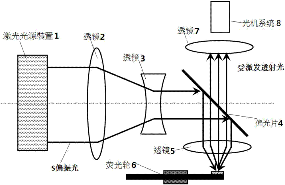
[0043] A light source system proposed by the present invention, such as image 3 As shown, the light source system includes: a laser light source device 1 , a lens or lens group, a polarizer 4 , a fluorescent wheel device 6 and an optical-mechanical system 8 . The laser light emitted by the laser light source device 1 is reflected by the polarizer 4 after passing through the lens or lens group, and then enters the fluorescent wheel device 6 after being transmitted through the lens 5. After the wavelength is converted by the fluorescent wheel device 6, the received laser light in the form of Lambertian divergent light , and then enter the optomechanical system 8 through the polarizer 4 .

[0044] The laser light source device 1 has a single polarization characteristic. At present, the 445nm / 30W laser light source produced by Nichia Corporation of Japan is widely used, but other laser light sources can also be used. In order to ensure the light output effect of the light source...

Embodiment 2

[0061] Another light source system proposed by the present invention, such as Figure 9 As shown, the light source system includes: a laser light source device 1', a lens or lens group, a polarizer 4', a lens 5', a fluorescent wheel device 6' and an optical-mechanical system 8'. The laser light emitted by the laser light source device 1' passes through the lens or lens group, and then enters the fluorescent wheel device 6' after being transmitted through the polarizer 4' and the lens 5'. After the wavelength is converted by the fluorescent wheel device 6', it produces light in the form of Lambertian The received light is transmitted through the lens 5' and reflected by the polarizer 4' into the optical mechanical system 8'.

[0062] In this embodiment, the spectra before and after the laser passes through the fluorescent wheel device are as follows: Figure 10 As shown, the polarizer is coated by coating technology to form a spectral region that transmits P polarized light an...

Embodiment 3

[0067] The difference between this embodiment and Embodiments 1 and 2 is that the polarizers of Embodiments 1 and 2 are replaced with filters, and the structure of the rest of the optical path remains unchanged. The spectrum of the filter refers to Figure 11 , its coating spectrum Slop Tavg 10% ~ Tavg 90% is less than 10nm, even as small as 5nm or less.


PUM


Abstract

The invention relates to a fluorescent wheel device, which comprises a fluorescent wheel substrate and multi-colored fluorescent powder, wherein the multi-colored fluorescent powder is sectionally attached to regions, irradiated by laser, of the fluorescent wheel substrate, and comprises blue fluorescent powder which emits blue excited light under the excitation of the laser. The invention further relates to a light source system comprising the fluorescent wheel device. The fluorescent wheel device and the light source system adopt a method of exciting all RGBY color light by using the fluorescent powder, do not need to design a special light path and structure for the blue light, so that the system is simple; and laser-free output can be realized, thereby achieving the purposes of being environmentally friendly and harmless.

Description

technical field [0001] The invention relates to an optical system, in particular to a fluorescent wheel device and a light source system. Background technique [0002] The light source of laser projectors currently uses blue light for excitation, such as figure 1 As shown, the light excited by the blue laser light source is converged onto the fluorescent wheel through the lens group, etc., and the fluorescent wheel is excited to produce red R, green G, and yellow Y colors of light, and the R, G, and Y colors of light pass through the lens group, color wheel, etc. focus to the entrance of the light pipe; the blue light of the laser itself passes through the gap on the fluorescent wheel or a transparent glass sheet, and then is reflected by the reflector, and finally focuses on the entrance of the light pipe and the color of R, G, and Y. Photosynthetic light. [0003] At present, R, G and Y colors of light are all excited by phosphors, and blue light is obtained by using an ...

Claims


Application Information

Patent Timeline
Patent Type & Authority Applications(China)
IPC IPC(8): G03B21/20
CPCG03B21/204G03B21/2073
Inventor 陈龙朴贤卿葛明星刘金根周建胜叶文彬
Owner 武汉视美乐激光显示发展有限公司
Learn More