
Hydraulic driving underwater drilling machine drill bit structure

A technology for driving water and drill bits, which is applied to drill bits, drilling equipment, earthwork drilling and production, etc. It can solve problems such as low degree of automation, easy wear and failure of circlips, and complicated coring process, achieving ingenious structural design and prolonging service life. , the effect of slowing down wear

Active Publication Date: 2017-12-15
GUANGZHOU INST OF GEOCHEMISTRY - CHINESE ACAD OF SCI +2
View PDF5 Cites 3 Cited by
  • Summary
  • Abstract
  • Description
  • Claims
  • Application Information

AI Technical Summary

Problems solved by technology

[0003] Domestic research in the field of seabed exploration equipment started relatively late. In recent years, it has begun to pay attention to research in this area. At present, the hydraulically driven underwater drilling rigs used to obtain reef-building coral core samples generally have a low degree of automation and require manual assistance. , strong dependence, low drilling rig operation efficiency
At present, for core extraction after drilling, most of them adopt the rope coring method. The coring process is relatively complicated. The sampling process requires three lifting operations to obtain a core sample once, which is time-consuming and labor-intensive.
However, in the existing circlip coring method, during the drilling process, the circlip rotates with the rock core or the core tube, and the circlip is prone to wear and tear. At the same time, the circlip cannot be tightened during the lifting process of the drill bit. The core is stuck, and the drill bit is lifted together, so that the core cannot be broken

Method used


Image

  • Hydraulic driving underwater drilling machine drill bit structure

Examples


Embodiment 1

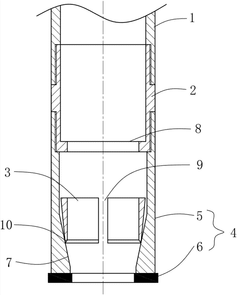
[0014] like figure 1 As shown, a drill bit structure of a hydraulically driven underwater drilling rig includes a core pipe 1 , a straight-through joint 2 , a retaining spring 3 and a drill bit 4 arranged coaxially. With the drilling direction of the drill bit 4 as the front, the front end of the core pipe 1 is threadedly connected to the rear end of the through joint 2. The drill bit 4 is an integrated structure formed by hot pressing of the drill steel body 5 at the rear end and the diamond matrix 6 at the front end. The inner wall of the rear end of the body 5 is threadedly connected with the front end of the through joint 2, and the inner wall of the front end is provided with an inverted conical surface 7. The minimum inner diameter of the inverted conical surface 7 is greater than the inner diameter of the diamond matrix 6, and the largest inner diameter is the inner wall aperture of the drill steel body 5. Circlip 3 is an inverted conical elastic tubular structure consi...


PUM


Abstract

The invention discloses a hydraulic driving underwater drilling machine drill bit structure. The hydraulic driving underwater drilling machine drill bit structure comprises a core barrel, a straight joint, a clamp spring and a drill bit which are coaxially arranged. The drill bit is of an integrated structure which is formed by a drill bit steel body and a diamond carcass through hot pressing, the clamp spring is of an inverted circular cone elastic tubular structure which is consistent with the conicity of the inverted circular cone face, an axial opening is formed in the side wall and installed in the drill bit steel body, and an inward annular boss is arranged at the front end of the straight joint. According to the hydraulic driving underwater drilling machine drill bit structure, the structural design of the drill bit and the clamp spring is ingenious, using of the tools of the clamp spring, a clamp spring seat, a short circuit, a reamer and the like in a traditional core-taking process is simplified, in the drilling process, abrasion of the clamp spring and the clamp spring seat can be effectively slowed down, the service life is prolonged, the surface of the rock core is prevented from being damaged, in the core-taking process, the clamp spring seat extrudes the whole clamp spring inwards simultaneously, so that the clamp spring tightly clamps the rock core, the clamp sprig is effectively prevented from moving upwards along with the clamp spring seat, and therefore rock core drilling and taking can be completed with once operation.

Description

technical field [0001] The invention relates to marine exploration mechanical equipment, in particular to a hydraulically driven underwater drilling rig drill bit structure for obtaining reef-building coral cores. Background technique [0002] Reef-building corals, also known as reef-building corals, are mainly distributed in warm, transparent, and oligotrophic tropical shallow waters. Reef-building corals are very sensitive to environmental changes. The isotopes and elemental compositions in their calcium skeletons can be used to reconstruct high-resolution seawater temperature, salinity, pH, rainfall and other information. Today's hottest global change, ocean acidification, and the most direct carrier of human activities' impact on climate and environment. Therefore, the acquisition of reef-building coral core samples plays a vital role in the research and development of marine science. [0003] Domestic research in the field of seabed exploration equipment started relat...

Claims


Application Information

Patent Timeline
Patent Type & Authority Applications(China)
IPC IPC(8): E21B10/02E21B10/48E21B7/124E21B25/18
CPCE21B7/124E21B10/02E21B10/48E21B25/18
Inventor 曾提孙彦敏韦刚健邓文峰陈洪舟刘燕辉黄永春
Owner GUANGZHOU INST OF GEOCHEMISTRY - CHINESE ACAD OF SCI
Learn More