
Bridge gap residue removing device with water spraying device

A technology of water spraying device and clearing device, which is applied in the direction of road surface cleaning, cleaning methods, construction, etc. It can solve the problems affecting the health of cleaners and pedestrians, affecting the expansion and contraction of bridges, and unfavorable bridge maintenance, so as to achieve strong cleaning power, easy operation, and application wide range of effects

Inactive Publication Date: 2017-12-15
夏新河
View PDF0 Cites 4 Cited by
  • Summary
  • Abstract
  • Description
  • Claims
  • Application Information

AI Technical Summary

Problems solved by technology

[0002] There are usually various preset gaps in the bridge, for example, the bridge expansion joints used to accommodate the changes in thermal expansion and cold contraction, for example, during the construction of the bridge deck, these expansion joints are easy to accumulate debris, which will be used later During the process, due to the influence of driving, foreign slag is easy to fall into these gaps. The long-term accumulation of slag affects the expansion and contraction of the bridge, which is not conducive to the maintenance of the bridge. Therefore, regular cleaning work is required
[0003] Existing solutions for removing these slags are often carried out manually, but this method has low efficiency, poor safety, waste of labor, and some positions and strengths of slag cannot be removed. During the cleaning process, fine dust will spread to the In the air, it will seriously affect the health of cleaning personnel and pedestrians. The invention provides a bridge gap residue removal device with a water spray device, which has high working efficiency, can completely remove residues, saves labor, and can improve the working environment of the staff. Wide range of applications

Method used

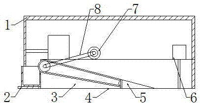

Image

  • Bridge gap residue removing device with water spraying device
  • Bridge gap residue removing device with water spraying device
  • Bridge gap residue removing device with water spraying device

Examples


specific Embodiment approach

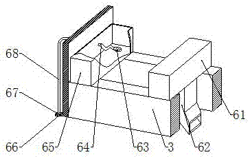
[0027] Specific implementation method: the staff fills up the water in the water tank 65 before use, is full of accumulator, connects the power supply of motor 7 during use, and negative pressure vacuum cleaner 61 starts to work, and fine residue is cleaned up by dust guide head 62, The design prevents the fine dust from being scattered in the air during the cleaning process, and solves the problem in the prior art that the fine dust is scattered in the air during the residue cleaning process and endangers people's health.

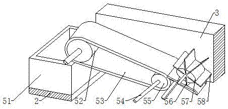
[0028] After the power supply of the motor 7 is turned on, the motor 7 drives the rotating shaft 54 ​​to rotate, and the rotating shaft 54 ​​connected to the drum 57 drives the drum 57 to rotate, thereby driving the cleaning brush 58 to move around the rotating shaft 54, and then sweeps the residue in the gap of the bridge into the guide plate 56 , the residue on the guide plate 56 continues to rise with the movement of the cleaning brush 58 until it falls ...


PUM


Abstract

The invention provides a bridge gap residue removal device with a water spray device, which includes a large roller, a rotating shaft, a small roller, a conveyor belt, a guide plate, a roller, a cleaning brush, a water tank, a water pump, a water pipe, an elbow, a high-pressure nozzle and a cleaning brush. The large roller is connected with the small roller through the conveyor belt, the guide plate is fixed on the front end of the small roller, the roller is installed on the top of the guide plate, and the cleaning brush is fixed on the outer surface of the roller. Difficult cleaning of debris. The water pump is installed inside the water tank. The elbow is connected to the water pump through the water pipe. The lower end of the elbow is equipped with a high-pressure nozzle, and the cleaning brush is installed at the lower part of the elbow. This design can further clean bridge gaps and solve the problem of the original technology. For the problems of difficult cleaning of stains in bridge gaps and solidified soil, the invention is easy to use, easy to operate, wide in scope of application and strong in cleaning power.

Description

technical field [0001] The invention relates to a bridge gap residue removal device with a water spray device, which belongs to the field of bridge gap residue removal equipment. Background technique [0002] There are usually various preset gaps in the bridge, for example, the bridge expansion joints used to accommodate the changes in thermal expansion and cold contraction, for example, during the construction of the bridge deck, these expansion joints are easy to accumulate debris, which will be used later During the process, due to the influence of driving, foreign slag is easy to fall into these gaps. The long-term accumulation of slag affects the expansion and contraction of the bridge, which is not conducive to the maintenance of the bridge, so it needs to be cleaned regularly. [0003] Existing solutions for removing these slags are often carried out manually, but this method has low efficiency, poor safety, waste of labor, and some positions and strengths of slag can...

Claims


Application Information

Patent Timeline
IPC IPC(8): E01H1/10
CPCE01H1/103
Inventor 夏新河
Owner 夏新河
Learn More