On-line denitrification process based on multi-stage circulation of sintering flue gas

A sintering flue gas and denitrification technology, applied in the field of online denitrification process, can solve the problems of difficult disposal of activated carbon, high operating cost, high cost, etc., achieve the effects of reducing the amount of gaseous pollutants produced, broad market application prospects, and reducing denitrification costs

Active Publication Date: 2020-04-03
武汉钢铁有限公司 +1
View PDF3 Cites 0 Cited by
  • Summary
  • Abstract
  • Description
  • Claims
  • Application Information

AI Technical Summary

Problems solved by technology

In the sintering machine flue gas purification projects of Japan's Nippon Steel Sumitomo Metal, JFE, South Korea's Posco, and China's Taiyuan Iron and Steel Co., Ltd., there are application cases for activated carbon (coke) to adsorb and purify pollutants in sintering flue gas, but the operation practice shows that the Large technical investment, high operating costs, low denitrification efficiency, and difficult disposal of waste activated carbon seriously restrict the large-scale promotion of this technology.
Selective catalytic reduction (SCR) has high denitrification efficiency, but its one-time investment cost is high (the catalyst cost accounts for 30-40% of the total investment cost), and the existing SCR flue gas denitrification technology is generally 350- It is carried out at 450°C, which consumes a lot of heat energy to heat the flue gas after desulfurization, which additionally increases the operating cost of SCR denitrification
Low-temperature denitrification catalysts are mostly noble metals, which are more expensive and prone to oxygen inhibition and sulfur poisoning

Method used


Image

  • On-line denitrification process based on multi-stage circulation of sintering flue gas
  • On-line denitrification process based on multi-stage circulation of sintering flue gas

Examples


Embodiment Construction

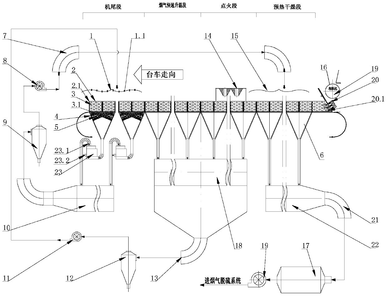
[0042] see figure 1 , the system used for the process of the present invention includes a sintering machine 2, a bellows 6 is provided under the trolley 2.1 of the sintering machine 2, and the sintering machine is successively divided into a preheating and drying section, an ignition section, and a flue gas rapid There are four regions of the heating section and the tail section. The wind box 6 below the tail section passes through the fluidized bed reactor 23, the high-temperature flue gas main flue 10, the high-temperature flue gas dust collector 9, the high-temperature flue gas circulation fan 8 and the The high temperature flue gas circulation pipe 7 is connected to the high temperature circulating flue gas hood 15 located above the preheating drying section. The outlet of the bellows 6 corresponding to the ignition section and the flue gas rapid heating section area is sequentially connected to the high NOx flue gas main flue 18, the high NOx flue gas circulation pipe 13,...


PUM


Abstract

The invention discloses a sintering smoke multi-stage circulating based online denitration technology. According to the technical scheme, the technology is characterized in that a sintering machine is sequentially divided into four areas, namely, a preheating drying section, an igniting section, a rapid smoke heating section and a tail section in a trolley marching direction; sintering smoke at the tail section is fed into a high-temperature circulating smoke hood through a main high-temperature smoke channel, a high-temperature smoke dust remover, a high-temperature smoke circulating fan and a high-temperature smoke circulating pipe in sequence; the sintering smoke in the igniting section and the rapid smoke heating section sequentially flows through a main high NOx smoke channel, a high NOx smoke dust remover and a high NOx smoke circulating fan and then is introduced into a high NOx circulating smoke hood; the sintering smoke enters a sintering material layer to be sintered gain; the sintering smoke in the preheating drying section flows through a main low-temperature smoke channel and then is exported through a low-temperature smoke pipe, an electrostatic / cloth bag type dust remover and a main air blower. The technology is small in pollutant emission, high in sintering smoke waste heat recovery rate, and free from external denitration catalysts, so that NOx in the smoke can be effectively decreased.

Description

technical field [0001] The invention relates to the field of environmental protection, in particular to an online denitrification process based on multi-stage circulation of sintering flue gas. Background technique [0002] In the belt draft sintering process, according to the temperature change of the sintering material layer and the physical and chemical changes in the sintering process, the material layer being sintered can be divided into 5 layers from top to bottom, which are sintered ore layer, combustion layer, Preheated layer, dry layer, over wet layer. After ignition, 5 layers appeared one after another, moving down continuously. Divided along the traveling direction of the belt-type sintering trolley, the sintering machine is divided into four areas, which are the ignition area, the low-temperature flue gas area, the flue gas rapid heating area, and the high-temperature flue gas area. [0003] There are large differences in the sintering flue gas temperature and ...

Claims


Application Information

Patent Timeline
Patent Type & Authority Patents(China)
IPC IPC(8): B01D53/86B01D53/56
CPCB01D53/8628B01D53/8631B01D2255/20738B01D2258/0283
Inventor 吴高明韩斌吴晓晖卫书杰
Owner 武汉钢铁有限公司
Why Eureka
Try Eureka