
Automatic winding device applicable to electromagnetic induction coils and winding method of automatic winding device

An electromagnetic induction coil and wire winding technology, which is used in the manufacture of inductors/transformers/magnets, circuits, electrical components, etc. The effect of processing cost, saving processing cost and avoiding short circuit

Active Publication Date: 2017-12-08
HENAN POLYTECHNIC UNIV
View PDF8 Cites 2 Cited by
  • Summary
  • Abstract
  • Description
  • Claims
  • Application Information

AI Technical Summary

Problems solved by technology

In these fields, the requirements for the winding quality of the coil are relatively high, and the coil needs to be wound neatly and regularly arranged tightly, and there are also strict requirements for the size and number of turns of the coil, especially when the size of the coil and the diameter of the enameled wire used are becoming more and more The smaller the occasion, the more difficult it is to use manual winding coils to meet the requirements. Although manual winding coils can save processing costs, the neatness and tightness of the coils formed by manual winding cannot be guaranteed, and it is more time-consuming; A small coil wound by a special machine can meet various requirements, but it increases the processing cost. For researchers doing experiments or processors of low-cost production, it is unrealistic to use a special machine to wind the coil due to the high cost.

Method used


Image

  • Automatic winding device applicable to electromagnetic induction coils and winding method of automatic winding device
  • Automatic winding device applicable to electromagnetic induction coils and winding method of automatic winding device
  • Automatic winding device applicable to electromagnetic induction coils and winding method of automatic winding device

Examples


Embodiment Construction

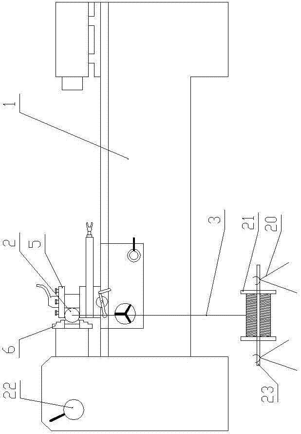
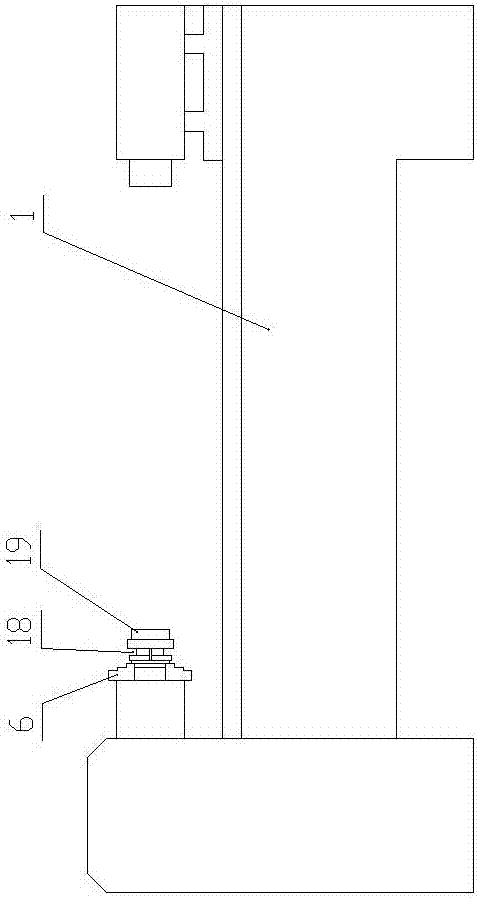
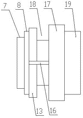
[0035] Such as Figure 1 to Figure 7 shown in figure 1 The left side of the left side is the left side of the present invention. A kind of automatic winding device suitable for electromagnetic induction coils of the present invention includes a horizontal lathe 1, a winding mold, a silica gel column 2 and an enameled wire 3, and the winding mold is fixed and clamped on On the horizontal lathe 1, the center of the silica gel column 2 is axially opened with a pre-tightening hole 4 for the enameled wire 3 to pass through. The diameter of the pre-tightening hole 4 is the same as that of the enameled wire 3, and the silica gel column 2 is fixed and clamped along the front and rear horizontal directions. On the tool post 5 of the horizontal lathe 1, one end of the enameled wire 3 passes through the pre-tightening hole 4 of the silica gel column 2 and the winding mold in turn, and is fixed with one of the jaws of the three-jaw chuck 6 of the horizontal lathe 1 by winding connect.

...


PUM


Abstract

An automatic winding device applicable to electromagnetic induction coils comprises a horizontal lathe, a winding mould, a silicon rubber column and an enameled wire. The winding mould is clamped on the horizontal lathe, the center of the silicon rubber column is axially provided with a pre-tightening hole for the enameled wire to penetrate, the silicon rubber column is horizontally and fixedly clamped on a tool rest of the horizontal lathe, and one end of the enameled wire penetrates the pre-tightening hole and the winding mould to be fixedly connected with a three-jaw chuck of the horizontal lathe. The winding mould comprises a sleeve, a left pressure plate, a right pressure plate and a clamping nut coaxially and sequentially arranged from left to right. The invention further discloses a winding method of the automatic winding device applicable to the electromagnetic induction coils. By joint use of the horizontal lathe and the winding mould, wire winding on the winding mould is performed on the horizontal lathe according to a thread lathing method, so that automatic winding of the electromagnetic induction coils is realized. Compared with manual winding, the automatic winding device has advantages of time saving, labor saving and capability of meeting small coil processing requirements.

Description

technical field [0001] The invention belongs to the field of ultrasonic processing and electromagnetic induction, and relates to an automatic thread winding device and a thread winding method suitable for electromagnetic induction coils. Background technique [0002] With the development of science and technology, more and more places need to use electromagnetic induction coils, such as: ultrasonic wireless transmission technology, energy storage electric water heaters heated by high-frequency induction coils, linear displacement sensors, electric toothbrushes, induction heaters and wireless Charging technology and more. In these fields, the requirements for the winding quality of the coil are high, and the coil needs to be wound neatly and regularly arranged closely, and there are also strict requirements for the size and number of turns of the coil, especially when the size of the coil and the wire diameter of the enameled wire used are increasing. The smaller the occasio...

Claims


Application Information

Patent Timeline
Patent Type & Authority Applications(China)
IPC IPC(8): H01F41/066H01F41/098H01F41/094
CPCH01F41/066H01F41/094H01F41/098
Inventor 童景琳冯浩人封志彬卫官向道辉崔峰赵俊帅陈鹏
Owner HENAN POLYTECHNIC UNIV
Learn More