
Sound insulation structure and method for manufacturing sound insulation structure

A technology of soundproofing and processing methods, which is applied in the direction of manufacturing tools, soundproofing, building components, etc., can solve the problems of large structure and difficulty in low-frequency shielding, and achieve the effect of strong soundproof structure, high sturdiness and light soundproof structure

Active Publication Date: 2017-11-28
FUJIFILM CORP
View PDF23 Cites 8 Cited by
  • Summary
  • Abstract
  • Description
  • Claims
  • Application Information

AI Technical Summary

Problems solved by technology

[0003] In this way, in most of the existing soundproof structures, the sound insulation is performed by the mass of the structure, so the structure becomes large and heavy, and there is a disadvantage that it is difficult to shield low frequencies

Method used


Image

  • Sound insulation structure and method for manufacturing sound insulation structure
  • Sound insulation structure and method for manufacturing sound insulation structure
  • Sound insulation structure and method for manufacturing sound insulation structure

Examples


Embodiment 1

[0109] Here, if Figure 6 ~ Figure 11 As shown, the film 18 fixed to the frame 14 of the soundproof unit 26 has the first natural frequency with the smallest transmission loss (for example, 0 dB), and the resonant frequency as the frequency of the lowest natural mode. In the present invention, the present inventors have found that since the first natural frequency is determined by the structure including the frame 14 and the membrane 18, as Figure 6 and Figure 7 As shown, the values ​​are substantially the same irrespective of the holes 22 pierced in the film 18 and further regardless of the presence or absence of the openings 24 . also, Figure 6 ~ Figure 11 These are graphs showing the sound insulation characteristics of the soundproof structures of Example 1 of the present invention, Comparative Example 1, and Examples 10, 21, 5, 23, and 38 of the present invention described later, and show transmission loss with respect to frequency.

[0110] Here, in the structure in...

Embodiment

[0195] The soundproof structure and the manufacturing method of the soundproof structure of this invention are demonstrated concretely based on an Example.

[0196]The design of the sound-proof structure is shown before the experiment to measure the acoustic properties was performed to manufacture an embodiment of the present invention.

[0197] The system of this soundproof structure is a system in which membrane vibration interacts with sound waves in the air, so it was analyzed using a coupling analysis of sound and vibration. Specifically, the sound module of COMSOLver5.0, which is the analysis software of finite element method, was used for design. First, the first natural frequency is obtained by natural vibration analysis. Next, an acoustic structural coupling analysis based on frequency sweep was performed in the boundary of the periodic structure, and the transmission loss at each frequency with respect to the sound wave incident from the front was obtained.

[0198...

Embodiment 2~7

[0220] A frame / film structure was produced in the same manner as in Example 1. It is known that the size of the hole 22 can be changed by changing the amount of heat generated by changing the laser irradiation time, so by optimizing the laser irradiation time / power, the desired hole 22 of 20 μm to 2000 μm can be obtained on the PET film. Table 3 shows the results including the shielding frequency in the soundproof structure of each Example thus obtained. also, Figure 10 The sound insulation characteristic of Example 5 is indicated by a dotted line in .


PUM


Abstract

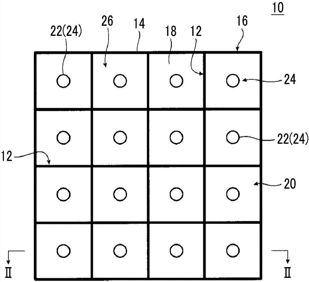
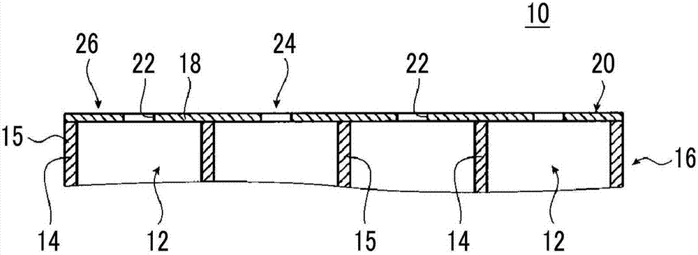
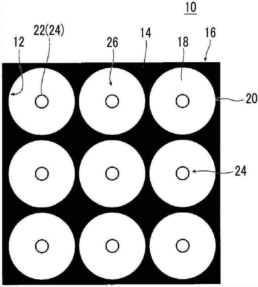
A sound insulation structure having one or more sound insulation cells, wherein: each of the one or more sound insulation cells is provided with a frame having through holes, a film affixed to the frame, and an opening part formed from one or more holes penetrating the film; both end parts of the through holes in the frame are not closed; and the sound insulation structure has, on the low-frequency side of a first natural resonance frequency for the film of the one or more sound insulation cells, a masking peak frequency that is determined due to the opening parts of the one or more sound insulation cells and for which transmission loss is maximum, and selectively insulates sound of a fixed frequency band centered on the peak masking frequency. Thus, it is possible to provide a sound insulating structure that is lightweight and thin, is not dependent on the position and shape of holes, has high robustness as an acoustic insulator, has stability, has air permeability, does not retain heat, and has excellent manufacturing suitability, and a manufacturing method for the sound insulating structure.

Description

technical field [0001] The present invention relates to a sound-proof structure and a method for manufacturing the sound-proof structure. Specifically, it relates to a sound-proof structure for selectively and strongly shielding sound of a target frequency including one or a plurality of two-dimensionally arranged sound-proof units. Structure, and the manufacturing method of the sound-proof structure for making this sound-proof structure. The soundproof unit has a frame, a film fixed to the frame, and an opening formed by one or more holes punched through the film. Background technique [0002] For common sound-insulating materials, the heavier the mass, the better the sound-shielding effect. Therefore, in order to obtain a good sound-insulating effect, the sound-insulating material itself becomes large and heavy. On the other hand, it is especially difficult to block out sounds of low-frequency components. Generally, this region is known as the mass law, and when the freq...

Claims


Application Information

Patent Timeline
Patent Type & Authority Applications(China)
IPC IPC(8): G10K11/16B23K26/00B23K26/382E04B1/86G10K11/162
CPCG10K11/162G10K11/172B23K26/382E04B1/86G10K11/16B23K26/00
Inventor 白田真也山添昇吾吉弘达矢大津晓彦笠松直史纳谷昌之
Owner FUJIFILM CORP
Learn More