Broadband adjustable real-time delay line circuit

An adjustable, delay line technology, applied in delay line applications, electrical components, pulse technology, etc., can solve the problems of limiting the effective bandwidth of the circuit, increasing power consumption, poor anti-interference ability, etc., and increasing the range of delay variation. , Improve the delay resolution, the effect of delay stability is good

Active Publication Date: 2020-07-31
SOUTHEAST UNIV
View PDF2 Cites 0 Cited by
  • Summary
  • Abstract
  • Description
  • Claims
  • Application Information

AI Technical Summary

Problems solved by technology

However, in the case of active device integration, circuit performance is often affected by changes in the external environment, and the anti-interference ability is poor, resulting in large delay deviations
In order to solve this problem, a feedback loop method is usually used to calibrate the delay, but this increases additional power consumption
At the same time, active devices tend to present higher impedances, causing lower poles that limit the effective bandwidth over which the circuit operates
At the same time, the delay time of an active circuit is usually inversely proportional to the operating bandwidth of the circuit. In order to achieve a large delay time range, the pole of the circuit will be relatively small, so the bandwidth will also be limited
The bandwidth of the active delay line circuit is small, and the delay time is relatively large, so the delay resolution will be reduced, and the amount of information and angle of processing will be limited.

Method used


Image

  • Broadband adjustable real-time delay line circuit
  • Broadband adjustable real-time delay line circuit
  • Broadband adjustable real-time delay line circuit

Examples


Embodiment Construction

[0010] The technical solution of the present invention will be further described below in conjunction with the accompanying drawings.

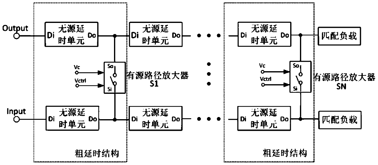
[0011] Such as figure 1 As shown, the broadband adjustable real-time delay line circuit of the present invention is mainly composed of cascaded N-stage coarse delay structures, each coarse delay structure includes a pair of passive delay units and an active path amplifier, the active path amplifier The source path amplifier is connected between two passive delay units, and the specific structure is: the input terminal Si and the output terminal So of the active path amplifier are respectively connected to the output terminal Do of a passive delay unit, forming a first-level coarse delay time structure; the input end of the coarse delay structure of the next stage is connected to the input end Si of the active path amplifier of the upper stage, and the output end of the coarse delay structure of the next stage is connected to the output end So ...


PUM


Abstract

The invention discloses a broadband adjustable real-time time delay line circuit which comprises a plurality of cascaded coarse time delay structures. Each coarse time delay structure comprises a pair of passive time delay units and an active path amplifier; each passive time delay unit consists of an inductor and a capacitor; and the active path amplifier is bridged between the output ends of the pair of passive time delay units to be used as a control switch for controlling delay time of the time delay line circuit. The corresponding active amplifier is selected to be conducted by a switch, a signal transmission path is changed, and coarse adjustment of time delay is carried out; and by regulating a bias circuit of the active path amplifier, fine adjustment of time delay is carried out, thereby implementing the time delay continuous change of fine adjustment and coarse adjustment. The circuit has the advantages of broadband, continuous adjustable time delay, wide time delay changing range, low power consumption and the like.

Description

technical field [0001] The invention relates to a delay line circuit, in particular to a broadband and adjustable real-time delay line circuit. Background technique [0002] With the continuous improvement of signal transmission rate requirements in wireless communication systems, multi-antenna broadband beamforming technology has become more and more important, and the real-time delay line circuit has become a key module that affects the signal receiving range and data transmission throughput. The delay resolution, delay range and signal working bandwidth of the delay line circuit determine the range of signal reception, maximum transmission rate and signal-to-noise ratio. Therefore, high delay resolution, wide delay range and wide operating bandwidth are the keys to improve the transmission quality of wireless communication systems. [0003] At present, the delay line circuit is mostly implemented in the form of optical devices, MEMS (Micro-Electro-Mechanical System, Micr...

Claims


Application Information

Patent Timeline
Patent Type & Authority Patents(China)
IPC IPC(8): H03K5/159
CPCH03K5/159H03K2005/00019
Inventor 李文渊陈阳王晏清
Owner SOUTHEAST UNIV
Why Eureka
Try Eureka