Design method of radar maneuvering target tracking waveform
A technology of maneuvering target tracking and waveform design, applied in the field of radar communication, can solve problems such as low accuracy and weak tracking robustness, and achieve the effects of improving tracking accuracy, avoiding mismatch of maneuvering targets, and good freedom
- Summary
- Abstract
- Description
- Claims
- Application Information
AI Technical Summary
Problems solved by technology
Method used
Image
Examples
specific Embodiment approach 1
[0027] Specific implementation manner 1: The method for designing radar maneuvering target tracking waveforms given in this implementation manner is specifically carried out according to the following steps:
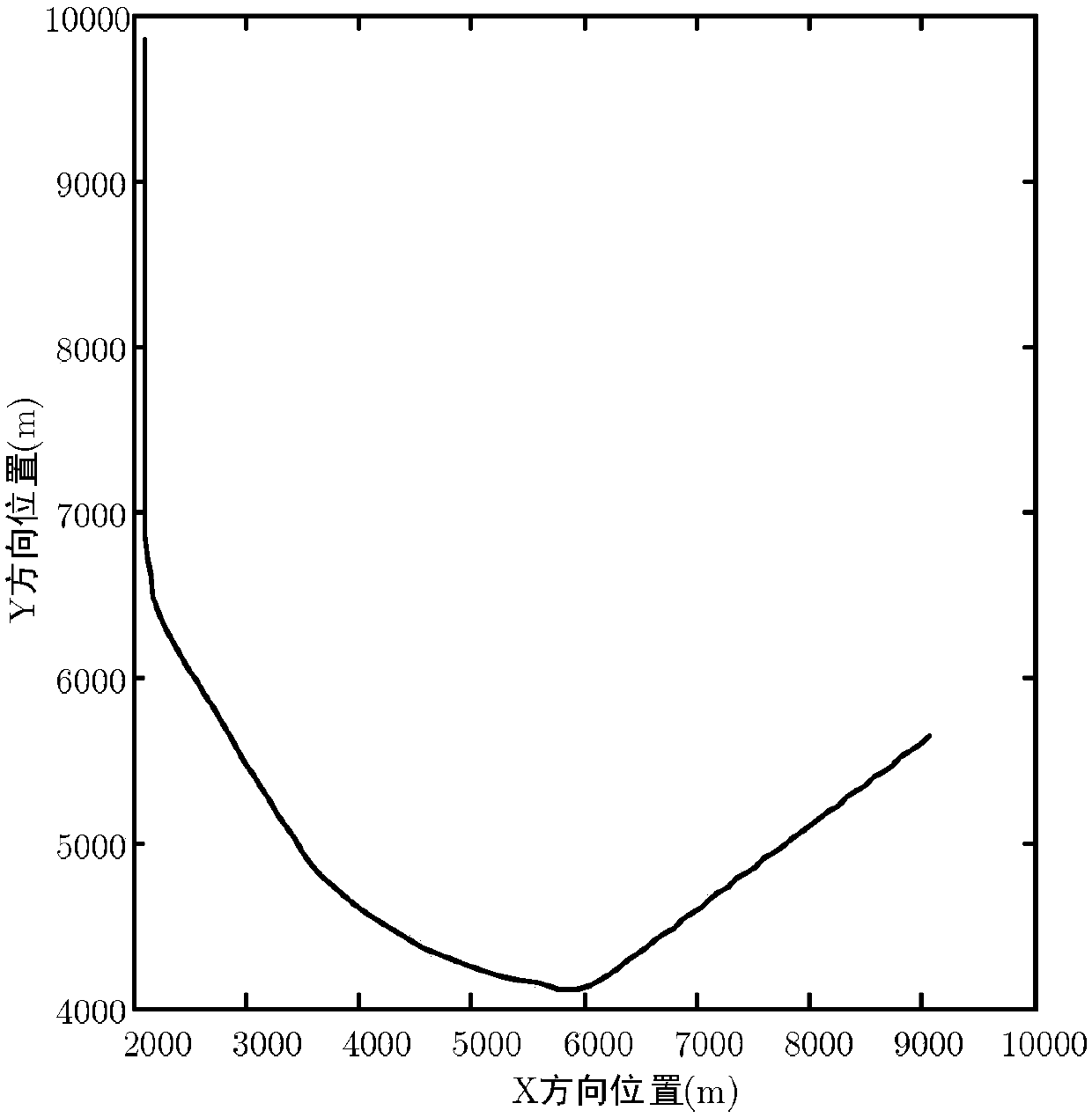
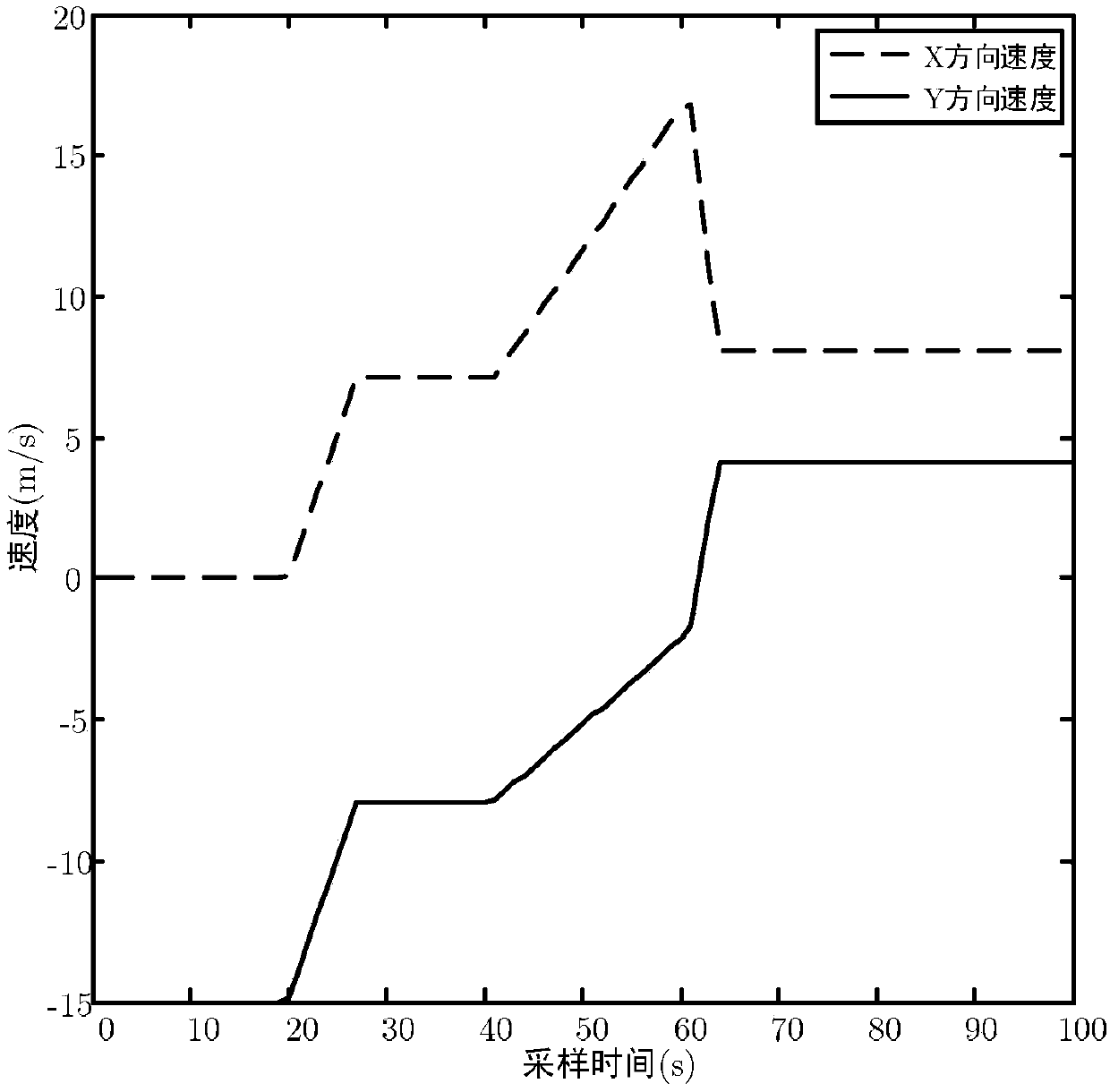
[0028] Step 1: Construct a motion model for the maneuvering target;
[0029] Step 2: Calculate the weights of the filter update matrix corresponding to the motion model;
[0030] Step 3: Calculate the mixed input state of the motion model and the corresponding estimated error covariance matrix;
[0031] Step 4. Use linear or non-linear filtering algorithm to obtain the local unbiased filter estimation and target state estimation error covariance matrix of each sub-model;
[0032] Step 5. Update the composite matrix to obtain the optimal fusion state estimation and the fusion estimation error covariance matrix;
[0033] Step 6. Obtain the transmission waveform rotation parameters based on the fusion estimation error covariance matrix, and use the fractional Fourier transform to rota...
specific Embodiment approach 2
[0035] Specific implementation manner 2: This implementation manner is different from the specific implementation manner one in that the construction of a motion model for a maneuvering target in the first step is specifically:
[0036]
[0037] The formula includes the target state equation x(k+1)=F j (x(k))+w j (k) and the measurement equation z(k) = H j (x(k))+v(k); x(k) represents the target state vector at time k, the dimension is n×1, including the position and speed state in the X and Y directions, z(k) is the measurement vector; j ∈{1,...,s} represents the model number in the model library, and s is the number of models; when the above formula represents a linear motion model, F j (·) and H j (·) is the linear transition matrix, when the nonlinear motion model is F j (·) and H j (·) represents a nonlinear function; w j (k) means that the mean is zero and the covariance matrix is Q j Gaussian process noise, v(k) represents the measurement noise with a mean value of zero an...
specific Embodiment approach 3
[0041] Specific embodiment three: This embodiment is different from the specific embodiment two in that the second step of calculating the weight of the filter update matrix corresponding to the motion model specifically includes the following steps:
[0042] For the state vector x, suppose the corresponding local unbiased filter estimates of s sub-models are Represents the local estimation error, Represents the i-th motion model The target state estimation error covariance matrix, Represents the motion model with The estimated error cross-covariance matrix of, and i≠j has Where E(·) is the expected value function; local unbiased filter estimation Can be regarded as the i-th motion model The corresponding filter's measurement of x is:
[0043]
[0044] Then you can define:
[0045]
[0046] among them:
[0047]
[0048] e=[I n ... I n ] T
[0049]
[0050] Unbiased knowledge which is I n Represents the n×n-dimensional unit matrix, e=[I n ... I n ] T Is a full-rank matrix; ...
PUM
 Abstract
Description
Claims
Application Information
 - R&D
- Intellectual Property
- Life Sciences
- Materials
- Tech Scout
- Unparalleled Data Quality
- Higher Quality Content
- 60% Fewer Hallucinations
Browse by: Latest US Patents, China's latest patents, Technical Efficacy Thesaurus, Application Domain, Technology Topic, Popular Technical Reports.
© 2025 PatSnap. All rights reserved.Legal|Privacy policy|Modern Slavery Act Transparency Statement|Sitemap|About US| Contact US: help@patsnap.com


