
A wide-beam dual-polarized microstrip antenna based on short-circuit wall structure

A microstrip antenna and short-circuit wall technology, which is applied to the antenna grounding device, radiating element structure, and antenna grounding switch structure connection, etc. The effect of increased power beamwidth, widened beamwidth, and large beamwidth

Active Publication Date: 2019-12-10
SYSU CMU SHUNDE INT JOINT RES INST +1
View PDF2 Cites 0 Cited by
  • Summary
  • Abstract
  • Description
  • Claims
  • Application Information

AI Technical Summary

Problems solved by technology

[0004] However, due to the defects of narrow beam width, narrow bandwidth, small gain, and low radiation efficiency, the traditional microstrip antenna is limited in many applications.
Especially at the receiving end of wireless energy transmission, the antenna is required to have higher effective receiving energy in a wider direction, and traditional antennas are more limited in this case

Method used


Image

  • A wide-beam dual-polarized microstrip antenna based on short-circuit wall structure
  • A wide-beam dual-polarized microstrip antenna based on short-circuit wall structure
  • A wide-beam dual-polarized microstrip antenna based on short-circuit wall structure

Examples


Embodiment 1

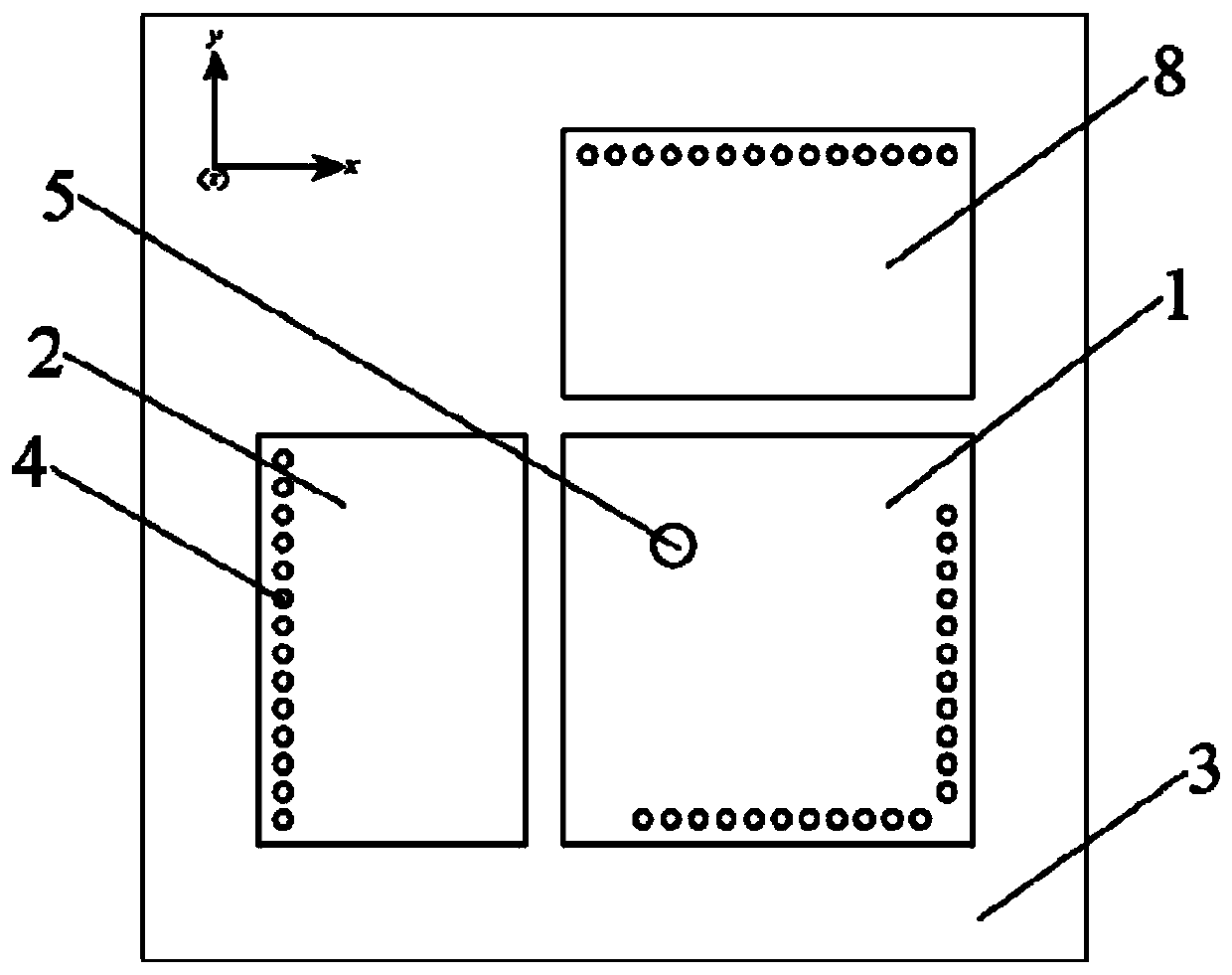
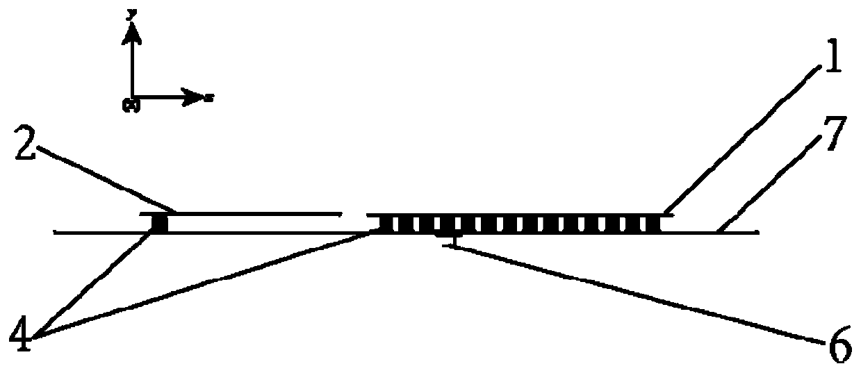
[0021] like figure 1 , 2 As shown, a wide-beam dual-polarized microstrip antenna based on a short-circuit wall 4 structure includes a main radiation patch 1, a substrate 3, a ground plane 7, a coaxial feed conductor needle 5, a first parasitic radiation patch 2 and The second parasitic radiation patch 8, wherein the main radiation patch 1 is arranged above the substrate 3, the ground plane 7 is arranged on the bottom surface of the substrate 3, and one end of the coaxial feed conductor needle 5 is connected with the main radiation patch 1, coaxial The other end of the feed conductor needle 5 passes through the substrate 3 and is connected to the ground plane 7; the first parasitic radiation patch 2 and the second parasitic radiation patch 8 are arranged above the substrate 3, and the first parasitic radiation patch 2 and the second parasitic radiation patch A central angle of 90 degrees is formed between the two parasitic radiation patches 8 with the main radiation patch 1 as...

Embodiment 2

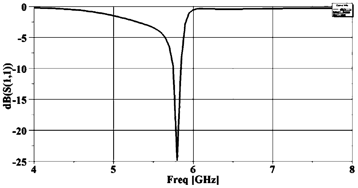
[0029] This embodiment has carried out concrete experiment to the microstrip antenna that embodiment 1 provides, and its experimental result is as follows image 3 , 4 shown.

[0030] like image 3 As shown, the microstrip antenna provided by Embodiment 1 has an optimal reflection coefficient s11=-24.83dB at a resonant frequency of 5.8GHz.

[0031] like Figure 4 As shown, at the resonant frequency of 5.8 GHz for the microstrip antenna provided by Embodiment 1, the half-power beamwidths on the planes xoz and yoz perpendicular to each other in the vertical direction are HPBW=128° and HPBW=134° respectively.

[0032] Experiments have proved that the microstrip antenna provided by the present invention has large beam width, good directivity, small size and high radiation efficiency when used, and is suitable for various wireless communication application fields.


PUM


Abstract

The invention relates to a wide-beam dual-polarized micro-strip antenna which comprises a main radiation chip, a substrate, a ground plane and a coaxial feed conductor probe. The main radiation chip is arranged above the substrate. The ground plane is arranged on the bottom surface of the substrate. One end of the coaxial feed conductor probe is connected with the main radiation chip. The other end of the coaxial feed conductor probe is connected with the ground plane after passing through the substrate. The wide-beam dual-polarized micro-strip antenna further comprises a first parasitic radiation chip and a second parasitic radiation chip which are disposed above the substrate. The first parasitic radiation chip and the second parasitic radiation chip form a central angle of 90 degrees by using the main radiation chip as a center of circle. The main radiation chip, the first parasitic radiation chip, the second parasitic radiation chip are provided with short-circuit walls. The short-circuit wall comprises at least 8 short-circuit pins. One end of each short-circuit pin of the short-circuit wall is connected with the main radiation chip, the first parasitic radiation chip, and the second parasitic radiation chip. The other end of each short-circuit pin of the short-circuit wall is connected to the ground plane after passing through the substrate.

Description

technical field [0001] The invention relates to the field of wireless energy transmission, and more specifically relates to a wide-beam dual-polarization microstrip antenna based on a short-circuit wall structure. Background technique [0002] Wireless power transfer technology (MPT) refers to a process in which energy is transmitted from an energy source to an electrical load through wireless transmission. It converts electrical energy into microwaves, and allows the microwaves to be transmitted to the target position in free space, and then rectified and converted into DC electrical energy. , providing DC power supply. MPT can realize long-distance energy transmission, and has always been a research point that has attracted much attention. [0003] The MPT transceiver antenna is at the front end of the system, responsible for receiving or transmitting energy from free space, and is one of the most important components of the MPT system. In order to meet the performance r...

Claims


Application Information

Patent Timeline
Patent Type & Authority Patents(China)
IPC IPC(8): H01Q1/38H01Q1/48H01Q1/50
CPCH01Q1/38H01Q1/48H01Q1/50
Inventor 谭洪舟黄静文区俊辉路崇安德烈·安德烈尼克
Owner SYSU CMU SHUNDE INT JOINT RES INST
Learn More