
Photoelectric composite cable for high-definition multimedia transmission and manufacturing method thereof

A photoelectric composite cable, high-definition multimedia technology, applied in the direction of communication cables, cables, light guides, etc., can solve the problems of small transmission capacity, difficult separation of optical units and electrical units, slow speed, etc., to improve signal transmission rate and excellent bending resistance The effect of large performance and transmission capacity

Pending Publication Date: 2017-11-07
JIANGSU ZHONGTIAN TECH CO LTD
View PDF7 Cites 3 Cited by
  • Summary
  • Abstract
  • Description
  • Claims
  • Application Information

AI Technical Summary

Problems solved by technology

[0003] Existing data signal transmission mainly adopts coaxial cable, which has small transmission capacity, slow speed, and short distance. Data transmission is greatly affected by the environment and easily interfered by external signals, resulting in poor transmission effect and picture distortion.
At the same time, the existing photoelectric composite cables used for high-definition signal transmission often use flame-retardant polyolefin materials as the outer sheath, which has low long-term aging resistance, and the optical unit and the electrical unit are not easy to separate.

Method used


Image

  • Photoelectric composite cable for high-definition multimedia transmission and manufacturing method thereof
  • Photoelectric composite cable for high-definition multimedia transmission and manufacturing method thereof

Examples


Embodiment 1

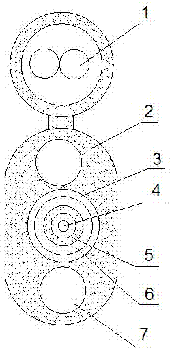
[0039] Take the 1-core tight-buffered optical fiber unit and the 2-core twisted-pair electrical unit as an example, which is designed as a flat structure, such as figure 1 As shown, a photoelectric composite cable for high-definition multimedia transmission, including an electrical unit 1, an optical unit, a reinforcing member 7 and an outer sheath 2, the upper and lower sides of the optical unit are provided with a reinforcing member 7, and the upper and lower sides of the optical unit are provided with an electrical unit 1. The outer sheath 2 wraps around the electrical unit 1, the reinforcing member 7 and the optical unit and forms an oval flat structure at the reinforcing member 7 and the optical unit. The electrical unit is an insulated electronic wire or a twisted pair, and the optical unit includes a central The tight-buffered optical fiber 4 is coated with a strengthening layer 5 outside the tight-bubbling optical fiber 4 , and the inner sheath 6 is extruded outside the...

Embodiment 2

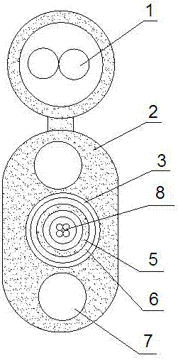
[0056] Taking the 4-core optical fiber microtube unit and 2-core twisted pair electric unit as an example, it is designed as a flat structure, such as figure 2 As shown, a photoelectric composite cable for high-definition multimedia transmission, including an electrical unit 1, an optical unit, a reinforcing member 7 and an outer sheath 2, the upper and lower sides of the optical unit are provided with a reinforcing member 7, and the upper and lower sides of the optical unit are provided with an electrical unit 1. The outer sheath 2 wraps around the electrical unit 1, the reinforcing member 7 and the optical unit and forms an oval flat structure at the reinforcing member 7 and the optical unit. The electrical unit is an insulated electronic wire or a twisted pair, and the optical unit includes a central The optical fiber microtube 8 is coated with a reinforcement layer 5 outside, the reinforcement layer 5 is extruded with an inner sheath 6, and the inner sheath 6 is longitudin...


PUM


Abstract

The present invention discloses a photoelectric composite cable for high-definition multimedia transmission. The cable comprises electrical units, an optical unit, reinforcers and over sheaths. The reinforcers are arranged at the upper side and the lower side of the optical unit, the upper portions of the reinforcers are provided with the electrical units, the electrical units, the reinforcers and the optical unit are coated with the over sheaths, the electrical units are insulation electron beams or twisted wires, the optical unit comprises a tight tube optical fiber or an optical fiber microtubule located at the center, a reinforcement layer is coated with the tight tube optical fiber or the optical fiber microtubule, the reinforcement layer performs external plastic extruding of an inner sheath, and the inner sheath is coated with a waterproof layer. The photoelectric composite cable has good stretching resistance and flattening resistance performances, the optical unit portion has water-blocking and flame retardation performances and good bending resistance performance and can be used in the outdoor hostile environment, the optical fiber is employed to perform data transmission to effectively perform interference resisting, the transmission distance is long, the transmission capacity is large, and the optical unit and the electrical units are easy to be separated so as to facilitate processing the composite cable into a connector module in later period.

Description

technical field [0001] The invention relates to the technical field of photoelectric composite cables, in particular to a photoelectric composite cable for high-definition multimedia transmission and a manufacturing method thereof. Background technique [0002] In recent years, indoor and outdoor dual-purpose optical cables have gradually been recognized by the market due to their convenient construction, various laying methods, and diversified applicable environments. At the same time, with the development of information technology, more and more high-definition intelligent multimedia devices are used, and people's experience of high-definition signal transmission is becoming more and more intense. [0003] The existing data signal transmission mainly adopts coaxial cable, which has small transmission capacity, slow speed, and short distance. Data transmission is greatly affected by the environment and easily interfered by external signals, resulting in poor transmission ef...

Claims


Application Information

Patent Timeline
Patent Type & Authority Applications(China)
IPC IPC(8): G02B6/44H01B11/22
CPCH01B11/22G02B6/443G02B6/4432G02B6/4434G02B6/4436G02B6/4479G02B6/44384
Inventor 汪趁时周华缪威玮
Owner JIANGSU ZHONGTIAN TECH CO LTD
Learn More