
Laser welding device and winding machine with same

A technology of laser welding and laser welding head, which is applied in the field of laser welding devices and winding machines, can solve problems such as poor welding, difficult control of cold welding time, uneven vibration amplitude and vibration frequency, etc., to prevent poor welding and good welding The effect of avoiding the increase of internal resistance

Pending Publication Date: 2017-11-07
东莞士格电子集团有限公司
View PDF5 Cites 2 Cited by
  • Summary
  • Abstract
  • Description
  • Claims
  • Application Information

AI Technical Summary

Problems solved by technology

[0003] Among them, the needles in the thorn riveting welding process are easy to oxidize and wear, and the rivet depths are different; at the same time, the pressure in the cold welding process is uneven, the mold is easy to wear, and the cold welding time is difficult to control; in addition, the vibration amplitude and vibration frequency in the ultrasonic welding technology Uneven, the mold is easy to wear
[0004] Based on the defects of the above-mentioned welding technology, poor welding effects such as poor welding, virtual riveting, and puncture are likely to occur when the guide pin or tab is connected to aluminum foil or copper foil in welding processes such as rivet riveting, cold welding, and ultrasonic welding, resulting in poor welding results. The internal resistance of the product becomes larger, which cannot meet the requirements of high-quality products; and the existing welding process cannot be accurately positioned

Method used


Image

  • Laser welding device and winding machine with same
  • Laser welding device and winding machine with same
  • Laser welding device and winding machine with same

Examples


Embodiment Construction

[0032] Embodiments of the present invention will now be described with reference to the drawings, in which like reference numerals represent like elements.

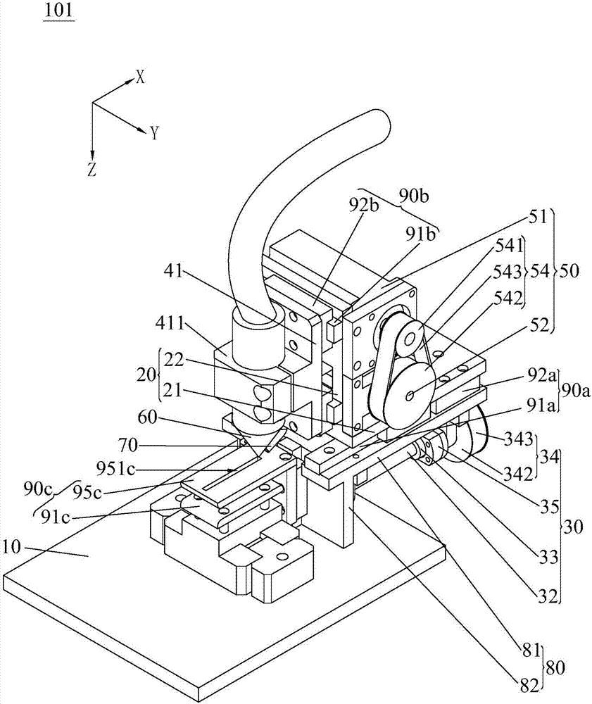
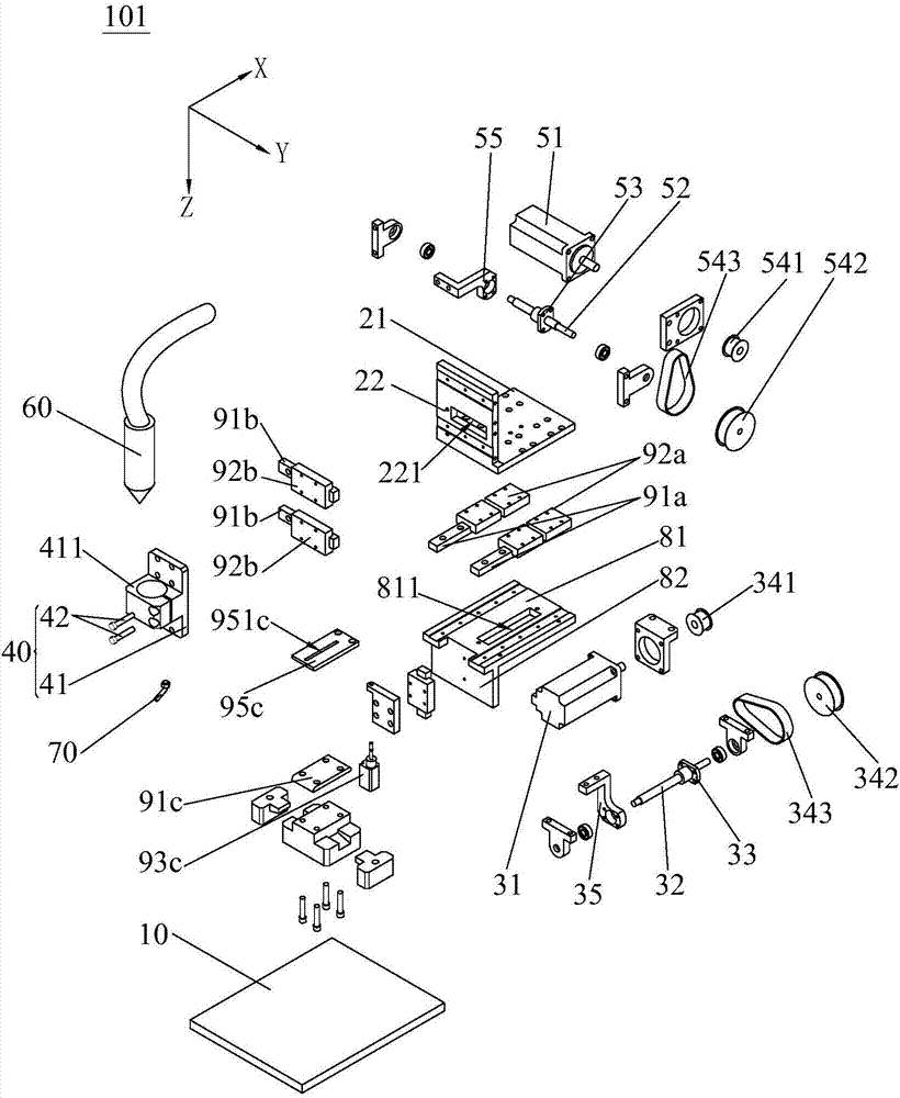
[0033] see Figure 1 to Figure 5, shows the laser welding device 101 of the first embodiment of the present invention, wherein, in the directions marked in the drawings, the X-axis represents the front-to-back direction, the Y-axis represents the left-right direction, and the Z-axis represents the vertical direction. The laser welding device 101 of this embodiment includes a base 10 , a sliding seat 20 , a first moving driving mechanism 30 , a locking mechanism 40 , a second moving driving mechanism 50 , a laser welding head 60 and an inert gas nozzle 70 . The sliding seat 20 is slidably arranged on the base 10 along the front-rear direction, the first mobile driving mechanism 30 is arranged on the base 10, and the first mobile driving mechanism 30 is transmission-connected to the sliding seat 20 to drive the sliding seat...


PUM


Abstract

The invention discloses a laser welding device. The laser welding device comprises a pedestal, a sliding seat, a first moving driving mechanism, a second moving driving mechanism, a holding and locking mechanism, a laser welding head and an inert gas nozzle. The sliding seat is slidably arranged on the pedestal in the front-back direction, and the first moving driving mechanism is arranged on the pedestal and is connected to the sliding seat in a transmission mode so as to drive the sliding seat to slide in the front-back direction. The holding and locking mechanism is slidably arranged on the sliding seat in the left-right direction, and the second moving driving mechanism is arranged on the sliding seat and is connected to the holding and locking mechanism in a transmission mode so as to drive the holding and locking mechanism to slide in the left-right direction. The laser welding head is clamped and fixed to the holding and locking mechanism in a vertical-position-adjustable mode, and the inert gas nozzle is fixed to the holding and locking mechanism. An outlet of the inert gas nozzle is aligned at the welding position of the laser welding head. The laser welding device is small and exquisite in structure and is arranged on a winding machine to replace a traditional device for thorn and rivet welding, cooling welding and ultrasonic welding.

Description

technical field [0001] The invention relates to the technical field of electronic product production equipment, in particular to a laser welding device and a winding machine with the device. Background technique [0002] With the upgrading of the industry, the demand for electronic products such as aluminum electrolytic capacitors, super capacitors, and batteries is increasing. At present, the production of electronic products such as aluminum electrolytic capacitors, super capacitors, and batteries requires welding the guide pins or tabs on aluminum foil or copper. Process link of soldering on foil. In the existing welding process, the guide pin or tab is mainly welded on the aluminum foil or copper foil by traditional rivet riveting, cold welding, ultrasonic welding technology, etc. However, the existing welding machine technology has the following defects: [0003] Among them, the needles in the thorn riveting welding process are easy to oxidize and wear, and the rivet d...

Claims


Application Information

Patent Timeline
Patent Type & Authority Applications(China)
IPC IPC(8): B23K26/21B23K26/70
CPCB23K26/21B23K26/702
Inventor 刘海湘
Owner 东莞士格电子集团有限公司
Learn More