
Tunable high-Q-value single-passband microwave photon filter

A microwave photon and optical filter technology, applied in the field of microwave photonics, can solve the problems of reducing the bandwidth of microwave photon filters, increasing Q value, and the influence of Q value, achieving high Q value, increasing Q value, shortening The effect of the round trip

Inactive Publication Date: 2017-10-27
HUAZHONG UNIV OF SCI & TECH
View PDF4 Cites 6 Cited by
  • Summary
  • Abstract
  • Description
  • Claims
  • Application Information

AI Technical Summary

Problems solved by technology

[0004] In view of the above defects or improvement needs of the prior art, the present invention provides a tunable high-Q value single-passband microwave photonic filter, which aims to solve the limitation of the existing microwave photonic filter due to the coherence of the optical signal in the optical loop And the problem that the Q value is affected, and the bandwidth of the microwave photon filter is further reduced by the feedback method, and the Q value is increased

Method used


Image

  • Tunable high-Q-value single-passband microwave photon filter
  • Tunable high-Q-value single-passband microwave photon filter
  • Tunable high-Q-value single-passband microwave photon filter

Examples


Embodiment 1

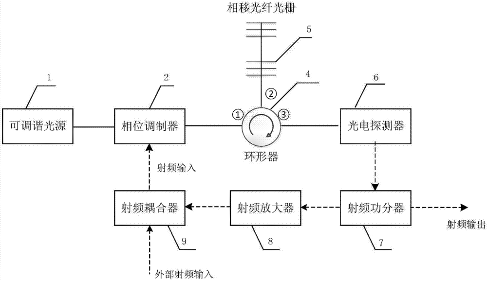
[0032] The tunable high-Q value single passband microwave photon filter that embodiment 1 provides, its structure is as follows figure 2 As shown; including a light source 1, an optical modulator 2, a circulator 4, a phase-shifting fiber grating 5, a photodetector 6, a radio frequency power splitter 7, and a radio frequency amplifier 8; also includes a radio frequency coupler 9; in this embodiment, the light source 1 adopts a tunable light source, and the optical modulator 2 adopts a phase modulator;

[0033] Wherein, the first end of the phase modulator is connected to the output end of the tunable light source, and the second end is used as a radio frequency signal interface for receiving radio frequency input; the first port ① of the circulator 4 is connected to the third end of the phase modulator, and the second The port ② is connected with the phase-shifting fiber grating 5; the first end of the photodetector 6 is connected with the third port ③ of the circulator 4, the...

Embodiment 2

[0038] The structure of the tunable high-Q value single-passband microwave photon filter based on the photoelectric feedback loop, dual-drive Mach-Zehnder modulator (DDMZM) and phase-shifting fiber grating provided by embodiment 2 is as follows figure 2 As shown; including a light source 1, an optical modulator 2, a circulator 4, a phase-shifting fiber grating 5, a photodetector 6, a radio frequency power divider 7 and a radio frequency amplifier 8; in this embodiment, the light source 1 adopts a tunable light source, and the optical Modulator 2 uses a dual-drive Mach-Zehnder modulator;

[0039] Among them, the first end of the dual-drive Mach-Zehnder modulator is connected to the output end of the tunable light source, and the second end is used as a radio frequency signal interface for receiving external radio frequency input; the first port ① of the circulator 4 is connected to the dual-drive Mach-Zehnder modulator. The third end of the Del modulator is connected, and the ...


PUM


Abstract

The invention discloses a tunable high-Q-value single-passband microwave photon filter. The tunable high-Q-value single-passband microwave photon filter comprises a light source, an optical modulator, an optical filter, a photoelectric detector, a radio frequency power divider and a radio frequency amplifier. The first end of the optical modulator is connected with the output end of the light source, the second end of the optical modulator serves as a first radio frequency interface for receiving external radio frequency input, and the fourth end of the optical modular serves as a second radio frequency interface for receiving internal radio frequency signals. The first end of the optical filter is connected with the third end of the optical modulator. The first end of the photoelectric detector is connected with the second end of the optical filter, the first end of the radio frequency power divider is connected with the second end of the photoelectric detector, and the second end of the radio frequency power divider serves as a radio frequency output interface. The first end of the radio frequency amplifier is connected with the third end of the radio frequency power divider, and the second end of the radio frequency amplifier serves as an internal radio frequency signal output interface. The tunable high-Q-value single-passband microwave photon filter has an extremely high Q value and can achieve a tunable single-passband filtering function.

Description

technical field [0001] The invention belongs to the technical field of microwave photonics, and more specifically relates to a tunable high-Q value single-pass band microwave photon filter. Background technique [0002] The microwave photonic filter is a device that modulates microwave signals onto optical carriers, uses optical devices to process the signals in the optical domain, and then performs photoelectric conversion to output microwave signals. Compared with traditional microwave filters, microwave photonic filters have the advantages of anti-electromagnetic interference, high operating frequency, large bandwidth, small size, light weight, and low loss. The method of microwave photonic filter processing signal is to load the microwave signal on different optical carrier taps, and then perform delay and weighted combination on the signal on each tap. According to whether the number of taps is limited, microwave photonic filters can be divided into two types: finite i...

Claims


Application Information

Patent Timeline
IPC IPC(8): G02F1/01
CPCG02F1/0121
Inventor 于源徐路
Owner HUAZHONG UNIV OF SCI & TECH
Learn More