


Quick Research
Generate reliable direction feasibility study reports for your R&D in just a few steps.

Technical Q&A
Discover and master advanced knowledge NOW. Basics, ideas, possibilities, all at once.

Find Solutions
As an expert in R&D theories, this can generate solutions to your technical problems instantly.

Evaluate Feasibility
Analyze your overall solution with one click, know your potential R&D risks in advance.

Monitor Landscape
Get weekly tech updates, stay abreast of the latest tech innovations and key insights.
Optical fiber F-P filter and preparation method thereof
A filter and optical fiber technology, which is applied in the field of optical fiber F-P filter and its preparation, can solve the problems of angle, translational dislocation, etc., and achieve the effects of improving filtering performance, solving end face offset dislocation, and convenient operation
- Summary
- Abstract
- Description
- Claims
- Application Information
AI Technical Summary
Problems solved by technology
Method used
Image


Examples
preparation example Construction
[0032] The preparation method of the present invention specifically comprises the following steps:
[0033] 1) Stripping the coating layer of the optical fiber to obtain the fiber core, and cleaning with alcohol;
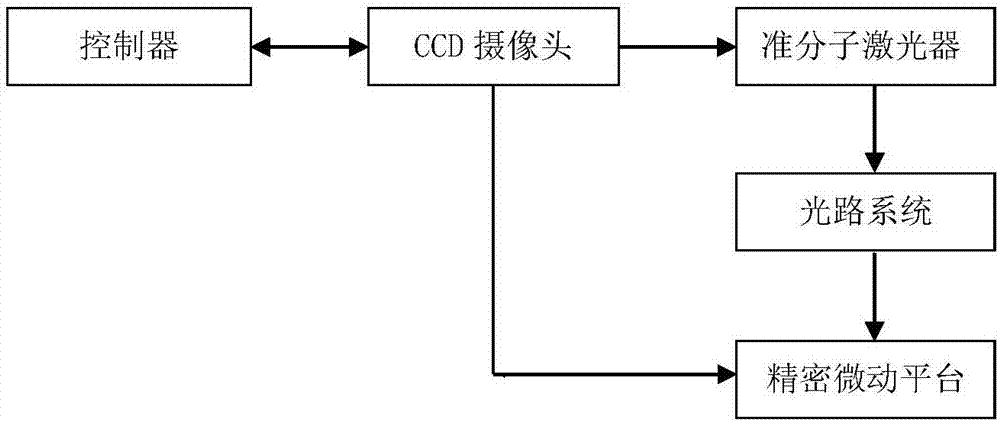
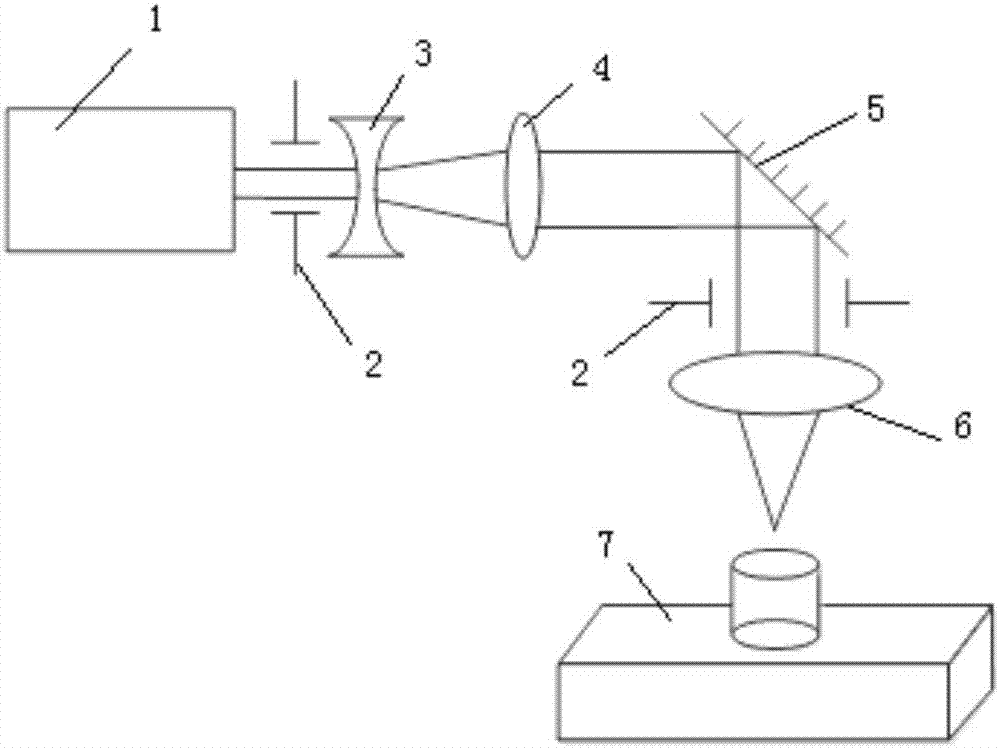
[0034] 2) Fix the fiber core on the glass slide, place the glass slide on the three-dimensional precision micro-motion platform, start the excimer laser, and adjust the three-dimensional precision micro-motion platform and the optical system to focus the laser spot on the central axis of the fiber core Location;
[0035] 3) Set the number of pulses of the excimer laser to 300 to 1000 times, the output wavelength of the excimer laser to 193nm, the pulse energy to 10 to 30mJ, and the frequency to 300Hz, and set the stepping movement value of the three-dimensional precision micro-motion platform to 0.5 to 4mm After the excimer laser is operated to drill the first microhole on the fiber core, the three-dimensional precision micro-motion platform drives the fiber core t...
Embodiment 1
[0040] Take a section of ordinary single-mode optical fiber, strip off the local coating layer by 5-10mm, and then fix it on the three-dimensional precision micro-motion platform. Through the controller, preliminarily adjust the X-axis (left-right direction) and Y-axis (front-rear direction) of the three-dimensional precision micro-motion platform, so that the uncoated area of the optical fiber is in the center of the field of view; then adjust the Z-axis of the three-dimensional precision micro-motion platform ( Up and down directions), so that the laser spot falls on the fiber; fine-tune the X-axis, Y-axis and Z-axis of the three-dimensional precision micro-motion platform again, so that the laser spot is focused on the center of the fiber; select the punching method (circular hole, rectangular hole, triangular hole), set the number of pulses output by the laser (300-1000), turn on the control switch for micro-hole processing, and the controller will stop after automatic co...
Embodiment 2
[0043] Processing multiple microholes at equal intervals on the optical fiber, Figure 6a and Figure 6b They are the top view and side view of the fabricated multi-fiber F-P cavity cascade filter respectively. During the production process, the stepping movement value of the platform in Example 1 is set to 3.5mm, then the first hole and the second hole can be realized The distance between the two holes is 3.5mm, and the distance between the second hole and the third hole is also 3.5mm. In this way, two optical fiber F-P filters with a cavity length of 3.5mm are cascaded to form a multi-fiber F-P cavity. Cascaded filter, its corresponding spectrum is as Figure 7 As shown, the free spectrum corresponding to its spectrum is 0.113nm, and the contrast is 5dBm.
[0044] According to the method described in embodiment 1 and embodiment 2, the porous structure optical fiber F-P filter can be processed on the optical fiber, Figure 8a It is the spectrogram of a cascaded F-P filter ...
PUM
| Property | Measurement | Unit |
|---|---|---|
| Diameter | aaaaa | aaaaa |
Abstract
Description
Claims
Application Information
 - R&D Engineer
- R&D Manager
- IP Professional
- Industry Leading Data Capabilities
- Powerful AI technology
- Patent DNA Extraction
Browse by: Latest US Patents, China's latest patents, Technical Efficacy Thesaurus, Application Domain, Technology Topic, Popular Technical Reports.
© 2024 PatSnap. All rights reserved.Legal|Privacy policy|Modern Slavery Act Transparency Statement|Sitemap|About US| Contact US: help@patsnap.com