
Novel Rack node medium plate and design method of the same

A node-in-board and design method technology, which is applied in data centers, electrical equipment structural components, cooling/ventilation/heating renovation, etc. The effect of fault reporting accuracy, guaranteeing time correctness, and improving processing capacity and efficiency

Active Publication Date: 2017-10-10
SUZHOU LANGCHAO INTELLIGENT TECH CO LTD
View PDF8 Cites 1 Cited by
  • Summary
  • Abstract
  • Description
  • Claims
  • Application Information

AI Technical Summary

Problems solved by technology

The mid-board of the existing node is designed with a simple MCU, which cannot meet the needs of the new Rack cabinet to quickly collect and control system information, be compatible with more models, and quickly handle faults

Method used


Image

  • Novel Rack node medium plate and design method of the same
  • Novel Rack node medium plate and design method of the same
  • Novel Rack node medium plate and design method of the same

Examples


Embodiment 1

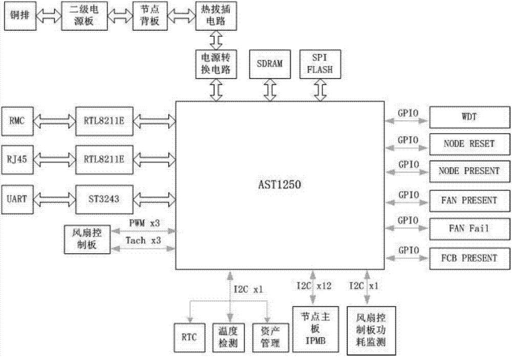
[0044] Such as Figure 1 to Figure 3 Shown, a kind of novel Rack node middle plate of the present invention, it comprises AST1250 chip, and AST1250 chip is connected with node module, fan module and node motherboard management controller respectively.

[0045] Such as figure 1 As shown, the new Rack node mid-board also includes GPIO interface, WDT, node RESET circuit (NODERESET), node presence detection circuit (NODE PRESENT), fan presence detection circuit (FAN PRESENT), fan status indicator control circuit ( FAN Fail), fan control board in-position detection circuit (FCB PRESENT), I2C bus, UART interface chip (ST3243), network chip (RTL8211E), SDRAM, SPI FLASH and power supply circuit, the AST1250 chip is respectively connected to WDT through GPIO interface , node RESET circuit, node in-position detection circuit, fan in-position detection circuit, fan status indicator control circuit and fan control board in-position detection circuit, AST1250 chip is connected with node m...

Embodiment 2

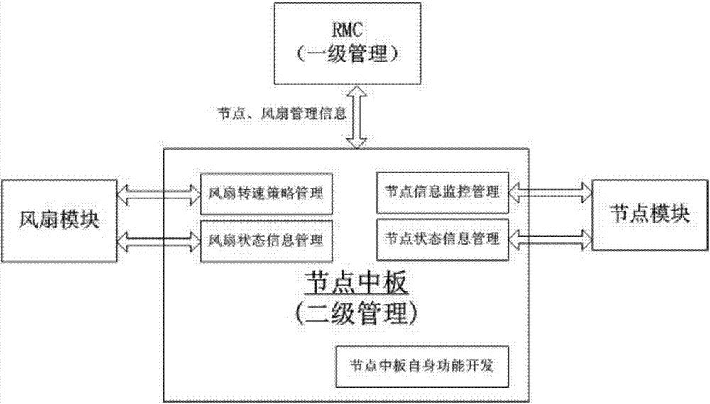
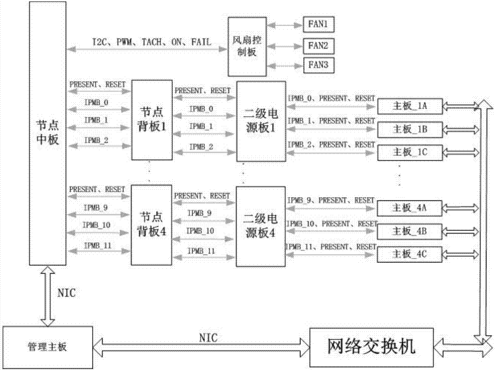
[0048] Such as Figure 1 to Figure 4 As shown, a novel Rack node midplane design method of the present invention, it realizes the design of the novel Rack node midplane by designing the management system functional block diagram, system interconnection topology and logic block diagram of the novel Rack node midplane.

[0049] Such as Figure 4 As shown, the novel Rack node mid-board design method includes the following specific steps:

[0050] Step S1, designing a functional block diagram of the board management system in the novel Rack node, the functions of the board management system in the novel Rack node include secondary management system functions, node management functions and fan management functions;

[0051] Step S2, designing the interconnection topology of the new Rack node mid-board system, wherein the new Rack node mid-board system interconnection topology includes the interconnection topology of the new Rack node mid-board and the node backplane, the secondary...


PUM


Abstract

The invention relates to a novel Rack node medium plate and a design method of the same. The novel Rack node medium plate includes an AST1250 chip, a node module, a fan module and a node mainboard management controller, wherein the node module, the fan module and the node mainboard management controller are connected with the AST1250 chip. The design method of the novel Rack node medium plate includes the following steps: S1, designing a novel Rack node medium plate management system function block diagram; S2, designing a novel Rack node medium plate management system interconnected topology; and S3, designing a novel Rack node medium plate logic block diagram. The novel Rack node medium plate uses the AST1250 to improve the Rack two-level management chip processing capability and efficiency. The node medium plate and the node BMC use a one-to-one I2C channel to realize quick acquisition and reporting of the node information. A WDT (WatchdogTimer) design is added, so that the product reliability is improved. An RTC function is added, the time correctness of system log is guaranteed and the fault reporting accuracy is improved. The node medium plate is communicated with the management mainboard through NIC, so that communication efficiency of Rack one-level management and two-level management.

Description

technical field [0001] The invention relates to a novel Rack node middle board and a design method thereof, belonging to the technical field of Rack server design. Background technique [0002] With the continuous development of the IT industry, the era of cloud computing and big data is coming. With the continuous expansion of Internet applications and the continuous growth of user business needs, high-density server cabinet systems have gradually become a trend. The emergence of Rack server cabinets just meets the development requirements of cloud computing and big data. This Rack server cabinet has a height of 46U. Computing nodes or storage nodes can be freely arranged in each U height space, and a maximum of 3 computing nodes can be deployed in 1U space. [0003] With the improvement of the data processing capability of the Rack server cabinet system, the increase of storage density, and the diversification of node types, higher requirements are put forward for the ma...

Claims


Application Information

Patent Timeline
IPC IPC(8): H05K7/14H05K7/20
CPCH05K7/1494H05K7/2019H05K7/20736
Inventor 肖沙沙郭猛
Owner SUZHOU LANGCHAO INTELLIGENT TECH CO LTD
Learn More