
Manufacturing method of abrasion-resisting layer of screw machine barrel

A production method and screw barrel technology, which are applied in the direction of manufacturing tools, furnace types, furnaces, etc., can solve the problems of unsatisfactory use effect, uneven heating of the alloy wear-resistant layer, and uneven surface of the alloy wear-resistant layer, etc. Small deformation, good heating effect and high power utilization

Active Publication Date: 2017-09-29
浙江华业塑料机械股份有限公司
View PDF6 Cites 6 Cited by
  • Summary
  • Abstract
  • Description
  • Claims
  • Application Information

AI Technical Summary

Problems solved by technology

This invention solves the difficult problem of centrifugal compound casting with conical double barrels. Under vacuum sintering, the alloy wear-resistant layer and the inner wall of the conical hole realize metallurgical bonding, which has higher bonding strength than inlaid cemented carbide materials, and is durable during use. The grinding layer will not fall off; however, the alloy wear-resistant layer of the machine barrel produced by this preparation method is not uniformly heated, so the surface of the alloy wear-resistant layer is not uniform enough, and the use effect is not ideal, so this method needs further improvement

Method used


Image

  • Manufacturing method of abrasion-resisting layer of screw machine barrel
  • Manufacturing method of abrasion-resisting layer of screw machine barrel
  • Manufacturing method of abrasion-resisting layer of screw machine barrel

Examples


Embodiment Construction

[0032] The present invention will be further described in detail below in conjunction with the accompanying drawings and embodiments.

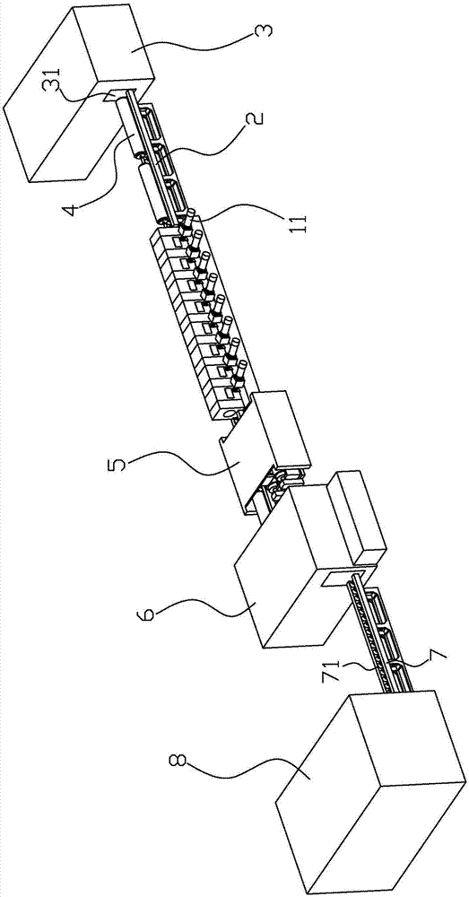
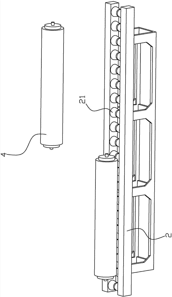
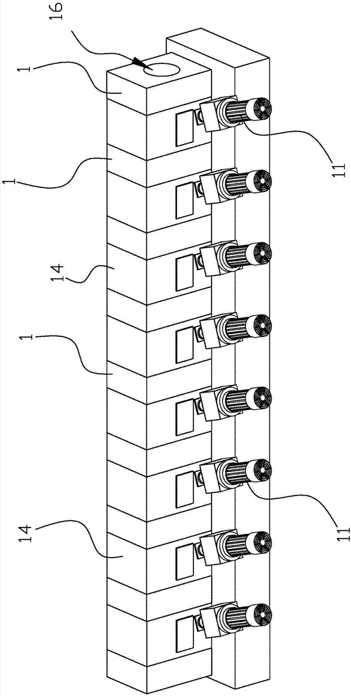
[0033] Such as Figure 1 to Figure 12 As shown, the manufacturing method of the screw barrel wear-resistant layer of the present embodiment includes the following steps,

[0034] 1. Add wear-resistant powder for making a wear-resistant layer into the inner cavity of the barrel 4, and seal the openings at both ends of the barrel 4 after the wear-resistant powder is loaded;

[0035] 2. Transport the barrel 4 to a heating furnace with a temperature of 1000-1300°C for heating. The barrel keeps rotating radially and moving back and forth in the axial direction when heating in the heating furnace, so that the resistant material placed in the inner cavity of the barrel 4 The grinding powder is evenly melted in the inner cavity of the barrel and covers the inner peripheral surface of the inner wall of the barrel, and at the same time, the melted wear...


PUM


Abstract

A manufacturing method of an abrasion-resisting layer of a screw machine barrel comprises the following steps that 1, abrasion-resisting powder is added into an inner cavity of the machine barrel (4), and openings of the two ends of the machine barrel (4) are sealed; 2, the machine barrel (4) is conveyed into a heating furnace with the temperature of 1000-1300 DEG C to be heated, and keeps rotating in the radial direction and moving back and forth in the axial direction while being heated in the heating furnace; 3, the machine barrel is subjected to centrifugation in a centrifugation part; and 4, the machine barrel (4) is conveyed to a heat preservation part after being subjected to centrifugation, tempering is conducted on the machine barrel, the machine barrel (4) is subjected to heat preservation in the heat preservation part of the machine barrel for 8-9 hours and then taken out from the heat preservation part, and then the machine barrel with the abrasion-resisting layer is prepared. The manufacturing method has the advantages that the defect that when a machine barrel is disposed in the heating furnace, the heating temperature of the two ends is low while the temperature of the middle is high is overcome, the abrasion-resisting powder disposed in the inner cavity of the machine barrel is heated evenly so as to be melted and oxidized at the same temperature, accordingly, molten liquid evenly covers the inner circumferential surface of the inner cavity of the machine barrel, and the abrasion-resisting layer is completely coincident in performance.

Description

technical field [0001] The invention relates to the technical field of machine barrel production, in particular to a method for making a wear-resistant layer of a screw machine barrel. Background technique [0002] There is a Chinese invention patent with the patent number CN201510537875.X titled "Preparation Method of High Wear-Resistant and Repairable Conical Double Barrel" which discloses a high wear-resistant and repairable conical double barrel The preparation method is that the round steel forging is firstly bored, and processed into a conical double-barrel blank with two intersecting inner holes and a cross-section in the shape of a figure-eight ring; ordinary steel is used to process it into the same taper as the inner hole of the barrel. Mandrel, the surface of two mandrels is spray-welded with a low-melting-point alloy wear-resistant layer, and the conical double-barrel mandrel is inserted into the blank hole of the barrel and pressed to form a barrel assembly; the...

Claims


Application Information

Patent Timeline
IPC IPC(8): B22D19/08C22C38/02C22C38/34C22C38/54C22C37/08C22C37/10C22C19/05B22D13/10C21D9/00
CPCB22D13/10B22D19/085C21D9/0068C22C19/058C22C37/08C22C37/10C22C38/02C22C38/34C22C38/54
Inventor 夏增富夏瑜键
Owner 浙江华业塑料机械股份有限公司
Learn More